3 selecting frequency of fout, 4 absolute max frequency on e1 and e2, Cs5466 – Cirrus Logic CS5466 User Manual
Page 12
CS5466
12
DS659F2
5.3.3
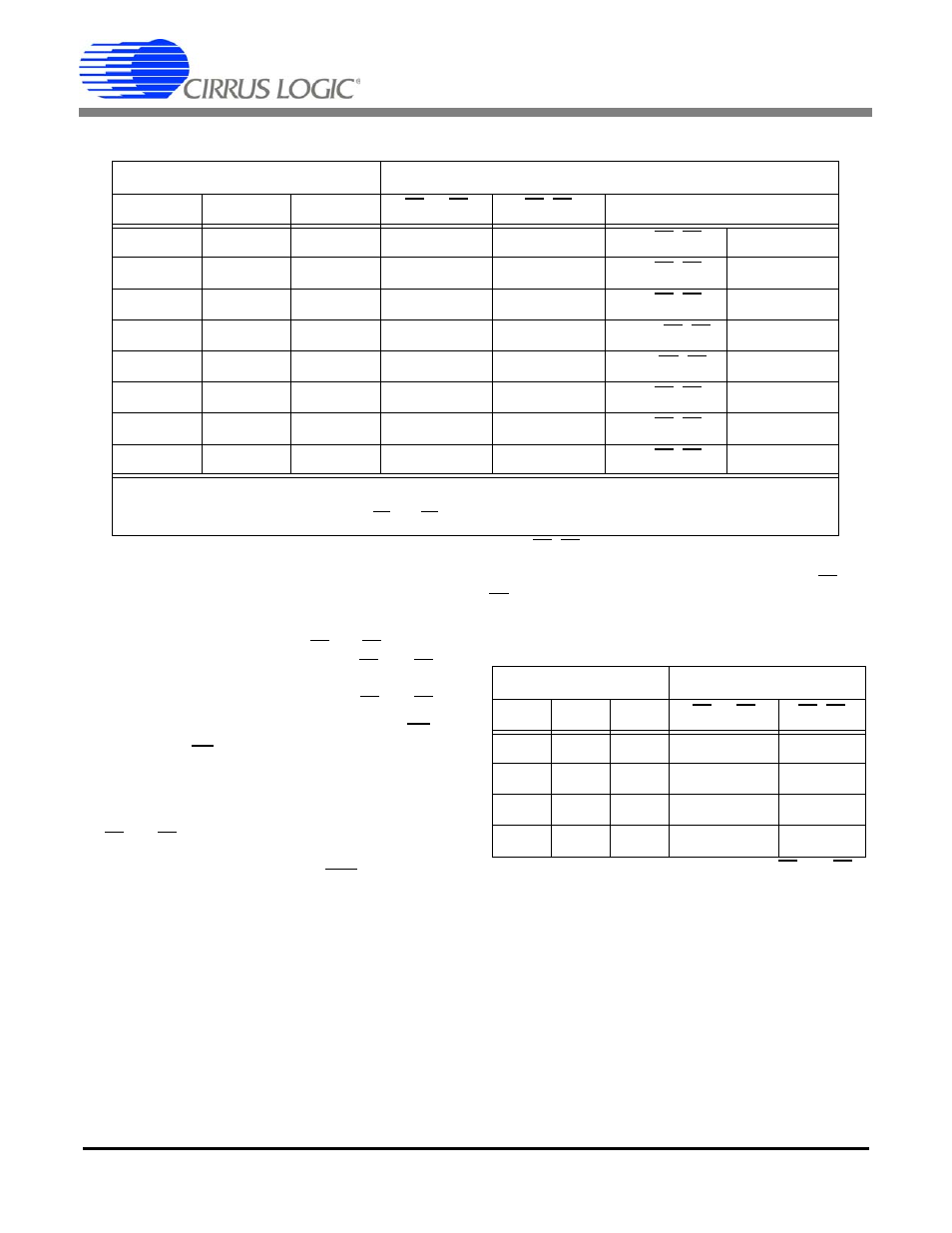
Selecting Frequency of FOUT
The pulse output FOUT is designed to assist with meter
calibration. Using the FREQ[2:0] pins, FOUT can be set
to frequencies higher than that of E1 and E2. The FOUT
frequency is directly proportional to the E1 and E2 fre-
quencies. Table 2 defines the maximum frequencies for
FOUT and the dependency of FOUT on E1 and E2.
5.3.4
Absolute Max Frequency on E1
and E2
The CS5466 supports input signals on the voltage and
current channels that may not be a sine wave. A typical
situation of achieving the absolute maximum frequency
on E1 and E2 would be if a 250 mV dc signal is applied
to the VIN and IIN input pins. The digital high-pass filter
should be disengaged by selecting HPF = 1.
The absolute maximum pulse rate observed on E1 and
E2, determined by the FREQ[2:0] selection is defined
below in Table 3.
Frequency Select
Maximum Frequency for a Sine Wave (Notes 1, 2 and 3)
FREQ2
FREQ1
FREQ0
E1 or E2
E1+E2
FOUT
0
0
0
0.125 Hz
0.25 Hz
64x(E1+E2)
16 Hz
0
0
1
0.25 Hz
0.5 Hz
32x(E1+E2)
16 Hz
0
1
0
0.5Hz
1.0 Hz
16x(E1+E2)
16 Hz
0
1
1
1.0 Hz
2.0 Hz
2048x(E1+E2)
4,096 Hz
1
0
0
0.125 Hz
0.25 Hz
128x(E1+E2)
32 Hz
1
0
1
0.25 Hz
0.5 Hz
64x(E1+E2)
32 Hz
1
1
0
0.5 Hz
1.0 Hz
32x(E1+E2)
32 Hz
1
1
1
1.0 Hz
2.0 Hz
16x(E1+E2)
32 Hz
Notes: 1 A pure sinusoidal input with zero phase shift is applied to the voltage and current channel.
2 MCLK = 4.096 MHz
3 See
for E1 and E2 timing diagram.
Table 2. Maximum Frequency for E1, E2, and FOUT
Frequency Select
Absolute Max Frequency
FREQ2 FREQ1 FREQ0
E1 or E2
E1+E2
x
0
0
0.25 Hz
0.5 Hz
x
0
1
0.5 Hz
1.0 Hz
x
1
0
1.0 Hz
2.0 Hz
x
1
1
2.0 Hz
4.0 Hz
Table 3. Absolute Max Frequency on E1 and E2