10 power offset register ( p, Cs5463 – Cirrus Logic CS5463 User Manual
Page 29
CS5463
DS678F3
29
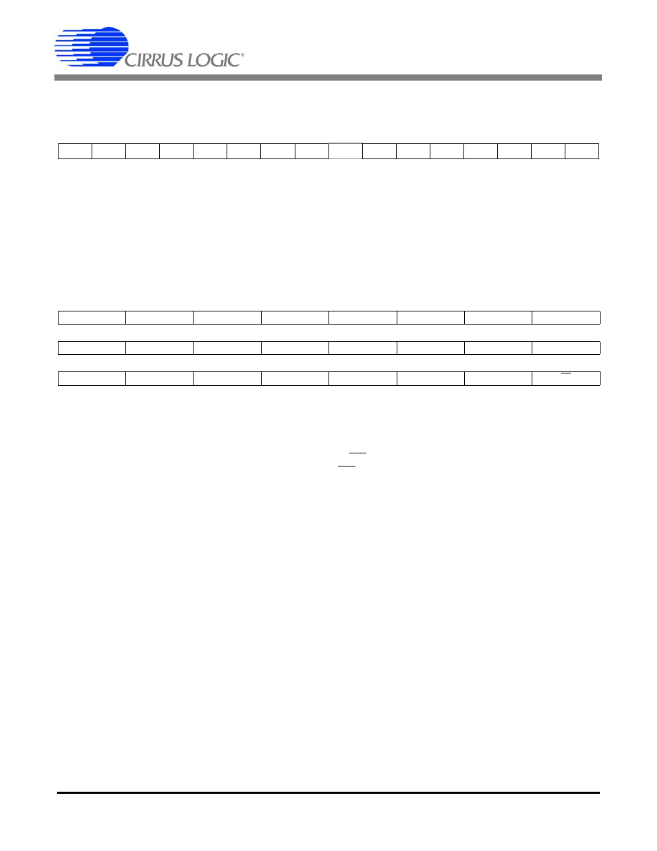
6.1.10 Power Offset Register ( P
off
)
Address: 14
Default = 0x000000
Power Offset (P
off
) is added to the instantaneous power being accumulated in the P
active
register, and can be
used to offset contributions to the energy result that are caused by undesirable sources of energy that are in-
herent in the system. The value is represented in two's complement notation and in the range of -1.0
P
off
1.0,
with the binary point to the right of the MSB.
6.1.11 Status Register and Mask Register ( Status , Mask )
Address: 15 (Status Register); 26 (Mask Register)
Default =
0x800001 (Status Register), 0x000000 (Mask Register)
The Status Register indicates status within the chip. In normal operation, writing a '1' to a bit will cause the bit
to reset. Writing a '0' to a bit will not change it’s current state.
The Mask Register is used to control the activation of the INT pin. Placing a logic '1' in a Mask bit will allow the
corresponding bit in the Status Register to activate the INT pin when the status bit is asserted.
DRDY
Data Ready. During conversions, this bit will indicate the end of computation cycles. For cali-
brations, this bit indicates the end of a calibration sequence.
CRDY
Conversion Ready. Indicates a new conversion is ready. This will occur at the output word rate.
IOR
Current Out of Range. Set when the Instantaneous Current Register overflows.
VOR
Voltage Out of Range. Set when the Instantaneous Voltage Register overflows.
IROR
I
RMS
Out of Range. Set when the I
RMS
Register
overflows.
VROR
V
RMS
Out of Range. Set when the V
RMS
Register
overflows.
EOR
Energy Out of Range. Set when P
ACTIVE
overflows.
IFAULT
Indicates a current fault has occurred. See Section 5.6
VSAG
Indicates a voltage sag has occurred. See Section 5.6
TUP
Temperature Updated. Indicates the Temperature Register has updated.
TOD
Modulator oscillation detected on the temperature channel. Set when the modulator oscillates
due to an input above full scale.
VOD (IOD)
Modulator oscillation detected on the voltage (current) channel. Set when the modulator oscil-
MSB
LSB
-(2
0
)
2
-1
2
-2
2
-3
2
-4
2
-5
2
-6
2
-7
.....
2
-17
2
-18
2
-19
2
-20
2
-21
2
-22
2
-23
23
22
21
20
19
18
17
16
DRDY
CRDY
IOR
VOR
15
14
13
12
11
10
9
8
IROR
VROR
EOR
IFAULT
VSAG
7
6
5
4
3
2
1
0
TUP
TOD
VOD
IOD
LSD
FUP
IC