Hardware, 1 introduction, 2 evaluation board overview – Cirrus Logic CDB5461AU User Manual
Page 4: 1 introduction 1.2 evaluation board overview, Figure 1. cdb5461au assembly drawing, Cdb5461au, Hardware 1.1 introduction
CDB5461AU
4
DS661DB1
1. HARDWARE
1.1
Introduction
The CDB5461AU evaluation board provides a quick means of evaluating the CS5461A Power Meter IC. The
CDB5461AU evaluation board operates from a single +5 V power supply. The evaluation board interfaces the
CS5461A to a PC via an USB interface. To accomplish this, the board comes equipped with a C8051F320 micro-
controller and a USB interface. Additionally, CDB5461AU GUI software provides easy access to the internal
registers of the CS5461A, and provides a means to display the performance in the time domain or frequency domain.
1.2
Evaluation Board Overview
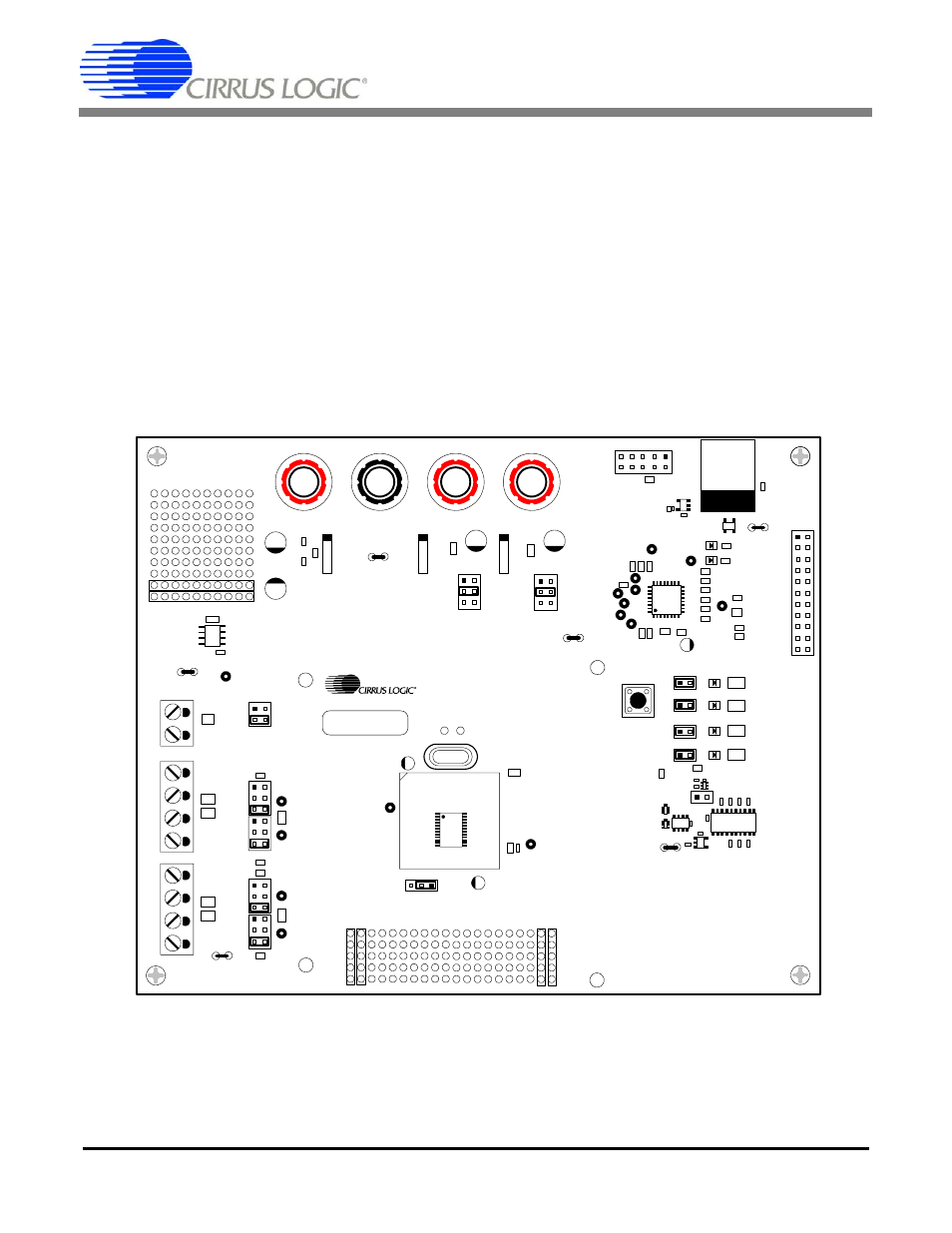
The board is partitioned into two main sections: analog and digital. The analog section consists of the CS5461A and
a precision voltage reference. The digital section consists of the C8051F320 microcontroller, EEPROM, the hard-
ware test switches, the reset circuitry, and the USB interface. The board also has a user friendly power supply con-
nection.
Figure 1. CDB5461AU Assembly Drawing
CDB5461AU REV X
JTAG
USB
J2
J6
Vu+_EXT
VD+_EXT
GND
+5V
J5
J4
J3
VIN+
VIN-
TP9
TP11
IIN+
IIN-
TP12
TP13
JP6
GND
GND
VREF
VIN+
VIN-
VREF
GND
GND
VREF
IIN+
IIN-
VREF
GND
GND
IIN+
IIN-
GND
GND
VIN+
VIN-
GND
REF+
GND
JP3
GND
J17
J22
J24
J26
J12
LT1019
REF+
J8
VD+_EXT
+5V
J9
+3.3V
VD+
Vu+_EXT
+5V
VD+
8051_REGIN
JP1
GND
JP2
GND
TP25
TP26
TP24
TP23
TP27
TP1
J10
1
J13
1
J15
1
J16
1
LED_EN
LED_EN
LED_EN
LED_EN
E1
E2
E3
MODE
J40
E1
E2
E3
INT
RESET
GND
JP5
TP10
CPUCLK
XU6
Y1
J25
VR
EF
VR
E
FI
N
V
RE
FOUT
VA+GND
VD+
GND
J14
J23
J27
GND
VD+
5
461A
RESET
S1
4.096MHz
TP7
TP8
XOUT XIN
U3
8051
U4
U5
J1
TP2
TP30
PFMON
MODE
EECS
CS
SCLK
MISO
MOSI
1
2
21
22
ERROR
EVENT
J18
1
AUTO-BOOT
ENABLE
U9
U11
U8
U2
U10
TP22
TP21
TP20
JP4
GND
U1
D1
U6
CDB5460A_61A_63