Typical connection diagrams, Cs53l21 – Cirrus Logic CS53L21 User Manual
Page 9
DS700PP1
9
CS53L21
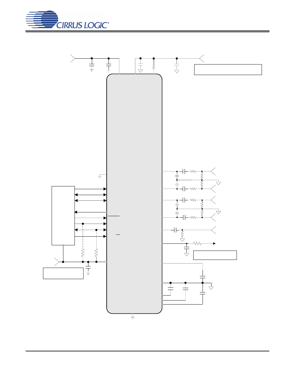
2. TYPICAL CONNECTION DIAGRAMS
Figure 1. Typical Connection Diagram (Software Mode)
1 µF
+1.8 V or +2.5 V
VQ
0.1 µF
1 µF
DGND
VL
0.1 µF
+1.8 V, +2.5 V
or +3.3 V
SCL/CCLK
SDA/CDIN
RESET
2 k
Ω
See Note 1
LRCK
AGND
AD0/CS
MCLK
SCLK
VD
* Capacitors must be C0G or equivalent
150 pF
AFILTA
AFILTB
MICIN1
AIN3A
Microphone Input
150 pF
SDOUT
CS53L21
2 k
Ω
1 µF
BIAS2
AIN3B/MICIN2
*
*
+1.8 V or +2.5 V
AIN1A
Left Analog Input 1
1800 pF
1800 pF
100 k
Ω
100
Ω
AIN1B
Right Analog Input 1
*
*
Note 1:
Resistors are required for I²C
control port operation
R
L
See Note 3
Note 3: The value of R
L
is dictated
by the microphone cartridge.
Digital Audio
Processor
0.1 µF
VA
AIN2A
Left Analog Input 2
1800 pF
1800 pF
AIN2B
BIAS1
Right Analog Input 2
*
*
10 µF
FILT+
Microphone Bias
1 µF
1 µF
1 µF
1 µF
1 µF
0.1 µF
100 k
Ω
100
Ω
100
Ω
100
Ω
100 k
Ω
100 k
Ω
100 k
Ω
See Note 4
Note 4:
Series resistance in the path of the power supplies must
be avoided.
TSTN
VA_
PULLUP
47 k
Ω
- CobraNet (147 pages)
- CS4961xx (54 pages)
- CS150x (8 pages)
- CS1501 (16 pages)
- CS1601 (2 pages)
- CS1601 (16 pages)
- CS1610 (16 pages)
- CRD1610-8W (24 pages)
- CRD1611-8W (25 pages)
- CDB1610-8W (21 pages)
- CS1610A (18 pages)
- CDB1611-8W (21 pages)
- CDB1610A-8W (21 pages)
- CDB1611A-8W (21 pages)
- CRD1610A-8W (24 pages)
- CRD1611A-8W (25 pages)
- CS1615 (16 pages)
- AN403 (15 pages)
- AN401 (14 pages)
- AN400 (15 pages)
- AN375 (27 pages)
- AN376 (9 pages)
- CRD1615-8W (22 pages)
- CRD1616-8W (23 pages)
- AN402 (14 pages)
- AN404 (15 pages)
- CRD1615A-8W (21 pages)
- CS1615A (16 pages)
- CS1630 (56 pages)
- AN374 (35 pages)
- AN368 (80 pages)
- CRD1630-10W (24 pages)
- CRD1631-10W (25 pages)
- CS1680 (16 pages)
- AN405 (13 pages)
- AN379 (31 pages)
- CRD1680-7W (31 pages)
- AN335 (10 pages)
- AN334 (6 pages)
- AN312 (14 pages)
- AN Integrating CobraNet into Audio Products (16 pages)
- CobraNet Audio Routing Primer (9 pages)
- Bundle Assignments in CobraNet Systems (3 pages)
- CS2300-01 (3 pages)
- CS2000-CP (38 pages)