2 hardware mode, Table 2. hardware mode feature summary, Cs53l21 – Cirrus Logic CS53L21 User Manual
Page 21
DS700PP1
21
CS53L21
4.2
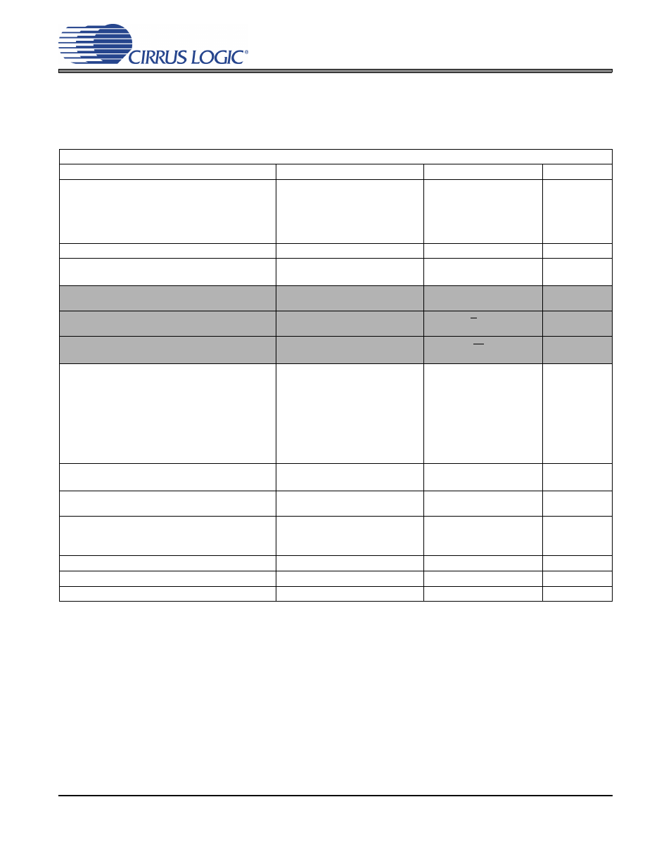
Hardware Mode
A limited feature-set is available when the A/D powers up in Hardware Mode (see
) and may be controlled via stand-alone control pins.
shows a list of func-
tions/features, the default configuration and the associated stand-alone control available.
Hardware Mode Feature/Function Summary
Feature/Function
Default Configuration
Stand-Alone Control
Note
Power Control
Device
PGAx
ADCx
MIC Bias
MICx Pre-Amplifier
Powered Up
Powered Up
Powered Up
Powered Down
Powered Down
-
-
Auto-Detect
Enabled
-
-
Speed Mode
Serial Port Slave
Serial Port Master
Auto-Detect Speed Mode
Single-Speed Mode
-
-
MCLK Divide
(Selectable)
“MCLKDIV2” pin 2
see Section
Serial Port Master / Slave Selection
(Selectable)
“M/S” pin 29
see Section
Interface Control
ADC
(Selectable)
“I²S/LJ” pin 3
see Section
ADC Volume & Gain
Digital Boost
Soft Ramp
Zero Cross
Invert
PGAx
Attenuator
ALC
Noise Gate
Disabled
Disabled
Disabled
Disabled
0 dB
0 dB
Disabled
Disabled
-
-
ADCx High-Pass Filter
ADCx High-Pass Filter Freeze
Enabled
Continuous DC Subtraction
-
-
Line/MIC Input Select
AIN1A to PGAA
AIN1B to PGAB
-
-
ADC mix Volume and Gain
Invert
Soft Ramp
Zero Cross
Disabled
Enabled
Enabled
-
-
Signal Processing Engine (SPE)
MIX
Disabled
-
-
Data Selection (SPE Enable)
ADC Data to SPE
-
-
Channel Swap
ADC
ADCA = L; ADCB = R
-
-
Table 2. Hardware Mode Feature Summary