9 recommended power-down sequence, Figure 17. initialization flow chart, Figure 17.initialization flow chart – Cirrus Logic CS53L21 User Manual
Page 33: T is shown in, Cs53l21
DS700PP1
33
CS53L21
4.9
Recommended Power-Down Sequence
To minimize audible pops when turning off or placing the A/D in standby,
1. Mute the ADC’s.
2. Set the PDN bit in the power control register to ‘1’b. The A/D will not power down until it reaches a fully
muted sate. Do not remove MCLK until after the part has fully muted. Note that it may be necessary to
disable the soft ramp and/or zero cross volume transitions to achieve faster muting/power down.
3. Bring RESET low.
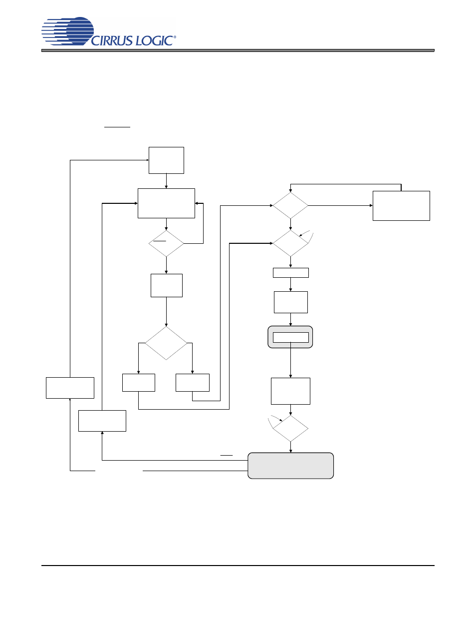
ADC Initialization
Software Mode
Registers setup to
desired settings.
RESET = Low?
No Power
1. No audio signal
generated.
Off Mode (Power Applied)
1. No audio signal generated.
2. Control Port Registers reset
to default.
Control Port
Active
Control Port Valid
Write Seq. within
10 ms?
Hardware Mode
Minimal feature
set support.
PDN bit = '1'b?
Sub-Clocks Applied
1. LRCK valid.
2. SCLK valid.
3. Audio samples
processed.
Valid
MCLK/LRCK
Ratio?
No
Yes
No
Yes
No
Yes
Yes
No
Normal Operation
Audio signal generated per control port or stand-
alone settings.
PDN bit set to '1'b
(software mode only)
Standby Mode
1. No audio signal generated.
2. Control Port Registers retain
settings.
Reset Transition
1. Pops suppressed.
Power Off Transition
1. Audible pops.
ERROR: Power removed
Valid
MCLK Applied?
No
20 ms delay
Charge Caps
1. VQ Charged to
quiescent voltage.
2. Filtx+ Charged.
2048 internal
MCLK cycle delay
RESET = Low
Figure 17. Initialization Flow Chart