C slave mode – Cirrus Logic CS4953xx User Manual
Page 17
CS4953xx Data Sheet
32-bit Audio Decoder DSP Family
DS705F2
17
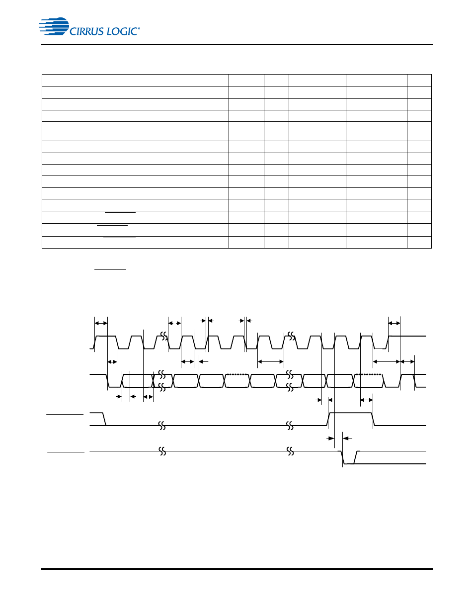
5.12 Switching Characteristics — Serial Control Port - I
2
C Slave Mode
Figure 5. Serial Control Port - I
2
C Slave Mode Timing
Parameter
Symbol
Min
Typical
Max
Units
SCP_CLK frequency
1
1. The specification f
iicck
indicates the maximum speed of the hardware. The system designer should be aware that
the actual maximum speed of the communication port may be limited by the firmware application. Flow control
using the SCP_BSY pin should be implemented to prevent overflow of the input data buffer.
f
iicck
—
—
400
kHz
SCP_CLK low time
t
iicckl
1.25
—
—
µs
SCP_CLK high time
t
iicckh
1.25
—
—
µs
SCP_SCK rising to SCP_SDA rising or falling for START or
STOP condition
t
iicckcmd
1.25
—
—
µs
START condition to SCP_CLK falling
t
iicstscl
1.25
—
—
µs
SCP_CLK falling to STOP condition
t
iicstp
2.5
—
—
µs
Bus free time between STOP and START conditions
t
iicbft
3
—
—
µs
Setup time SCP_SDA input valid to SCP_CLK rising
t
iicsu
100
—
—
ns
Hold time SCP_SDA input after SCP_CLK falling
2
2. This parameter is measured from the ViL level at the falling edge of the clock.
t
iich
0
—
—
ns
SCP_CLK low to SCP_SDA out valid
t
iicdov
—
—
18
ns
SCP_CLK falling to SCP_IRQ rising
t
iicirqh
—
—
3
*
DCLKP + 40
ns
NAK condition to SCP_IRQ low
t
iicirql
—
3
*
DCLKP + 20
—
ns
SCP_CLK rising to SCB_BSY low
t
iicbsyl
—
3
*
DCLKP + 20
—
ns
SCP_BSY
SCP_CLK
SCP_SDA
SCP_IRQ
0
1
6
7
8
0
1
7
t
iicckl
t
iicckh
t
iicsu
t
iich
A6
A0
R/W
ACK
LSB
t
iicirqh
t
iicirql
8
ACK
MSB
t
iicstp
6
t
iiccbsyl
t
iicdov
t
iicbft
t
iicstscl
t
iicckcmd
f
iicck
t
iicckcmd
t
iicf
t
iicr