1 time-division multiplex (tdm) mode, Figure 14. tdm mode connection diagram, Figure 15. tdm mode timing – Cirrus Logic CS4350 User Manual
Page 19: Cs4350
DS691F2
19
CS4350
4.3.1
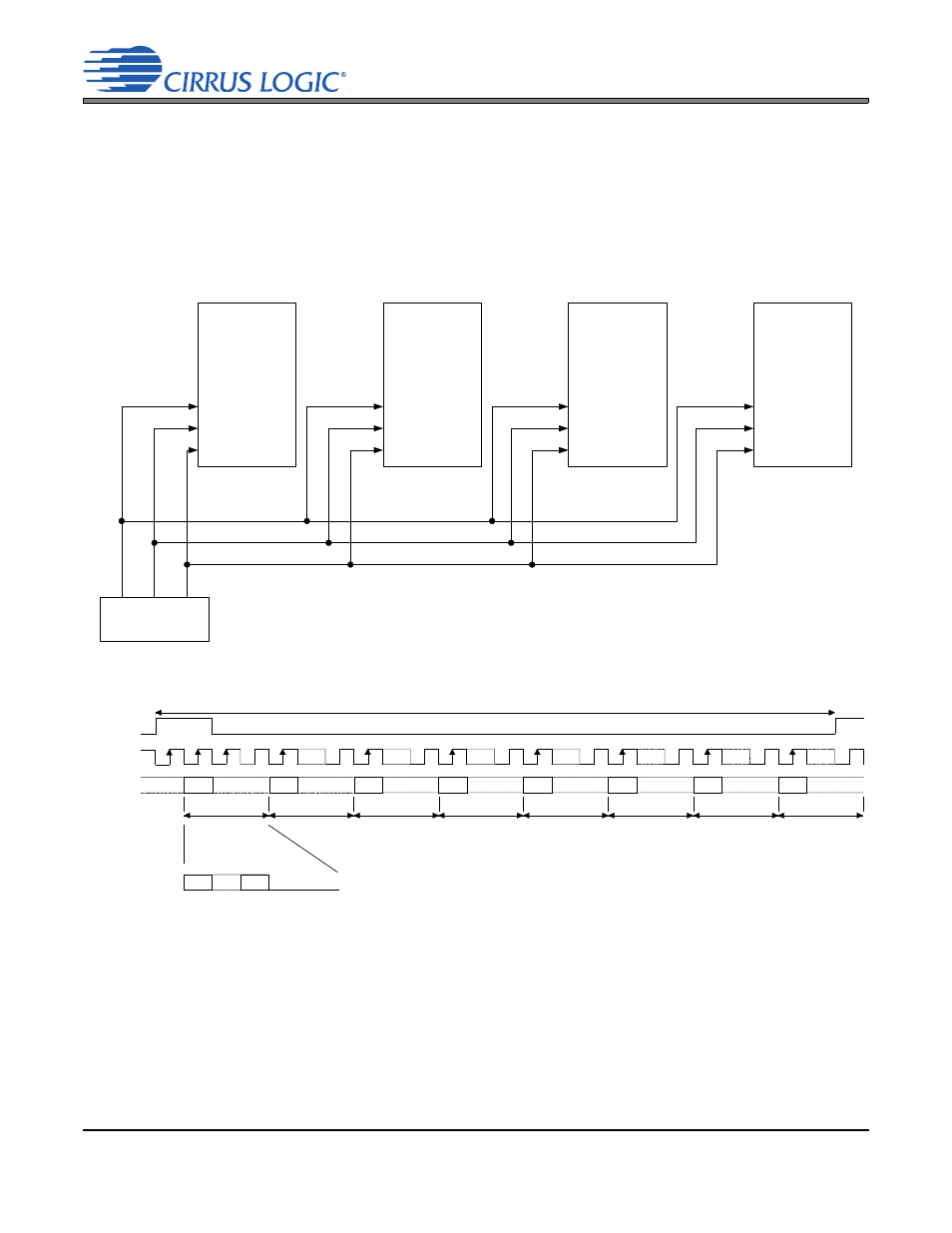
Time-Division Multiplex (TDM) Mode
Four TDM interface modes are available that allow the CS4350 to input stereo PCM data in one of 4 time
“slots”.
shows the serial port connections necessary to input 8-channel TDM data into four
CS4350 devices, and the corresponding DIF[2:0] pin or register-bit settings required for each CS4350.
shows the TDM data format for each of the four CS4350 devices shown in
.
Note:
The group delay for TDM slot 0 channel B differs from the group delay of all other interface for-
mats and TDM slots/channels by one sample. Refer to the group delay specification in the com-
bined interpolation and on-chip analog filter response specifications table.
.
LRCK
SCLK
SDIN
ILRCK
ISCLK
SDIN
LRCK
SCLK
SDIN
LRCK
SCLK TDM_OUT
TDM Source
CS4350
1
CS4350
2
LRCK
SCLK
SDIN
CS4350
3
DIF[2:0] = 100
DIF[2:0] = 101
DIF[2:0] = 110
DIF[2:0] = 111
CS4350
4
Figure 14. TDM Mode Connection Diagram
Slot 1, ch B
LRCK
SCLK
MSB
MSB
MSB
MSB
MSB
SDIN1
Slot 3, ch A
Slot 3, ch B
Slot 1, ch A
Slot 0, ch A
256 clks
32 clks
32 clks
32 clks
32 clks
32 clks
MSB
Slot 2, ch A
32 clks
MSB
Slot 0, ch B
32 clks
MSB
Slot 2, ch B
32 clks
LSB
MSB
zero
Data
Figure 15. TDM Mode Timing