Cirrus Logic CS4350 User Manual
Cs4350, Khz stereo dac with integrated pll, Features
Copyright
Cirrus Logic, Inc. 2013
(All Rights Reserved)
192-kHz Stereo DAC with Integrated PLL
Features
Advanced multibit delta-sigma architecture
109 dB dynamic range
-91 dB THD+N
24-bit conversion
Supports audio sample rates up to 192 kHz
Low-latency digital filtering
Single-ended or differential analog output
architecture
Integrated PLL locks to incoming left-right
clock
– Eliminates the need for external master-
clock routing
– Reduces interference and jitter sensitivity
– No external loop filter components required
Automatic sample-rate range detection
Popguard
®
technology for control of clicks and
pops
Hardware popguard disable for fast startups
Supports all standard serial audio formats
including time-division multiplexed (TDM)
+1.5- to 5.0-V logic supplies for serial port
+3.3- to 5.0-V control port interface
Control Port Mode Features
SPI™ and I²C
™
Modes
ATAPI mixing
Mute control for individual channels
Digital volume control with soft ramp
– 127.5 dB attenuation
– 1/2 dB step size
– Zero-crossing click-free transitions
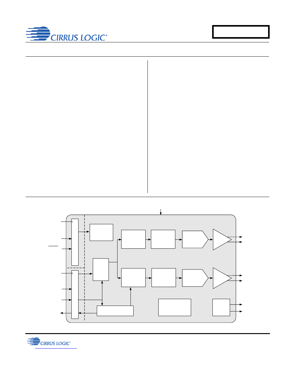
PCM
Serial
Interface
Serial Audio Input
Right
Channel
Output
Left
Channel
Output
Reset
3.3 V to 5.0 V
Register/
Hardware
Configuration
Hardware or I
2
C/
SPI Control Data
3.3 V to 5.0 V
LRCK
RM
CK
RMCK
Recovered MCLK
1.5 V to 5.0 V
Internal Voltage
Reference
and Regulation
Phase Locked Loop
Interpolation
Filter with
Volume
Control
Interpolation
Filter with
Volume
Control
Multibit
Modulator
Multibit
Modulator
L
e
ve
l T
ransla
tor
Le
ve
l Transl
a
tor
Amp
+
Filter
Amp
+
Filter
Left and
Right Mute
Controls
External
Mute
Control
DAC
DAC
APR ‘13
DS691F2
CS4350
Document Outline
- 192-kHz Stereo DAC with Integrated PLL
- 1 Pin Description
- 2 Characteristics and Specifications
- 2.1 Recommended Operating Conditions
- 2.2 Absolute Maximum Ratings
- 2.3 DAC Analog Characteristics - Commercial (-CZZ)
- 2.4 DAC Analog Characteristics - Automotive (-DZZ)
- 2.5 Combined Interpolation and On-Chip Analog Filter Response
- 2.6 Switching Specifications - Serial Audio Interface
- 2.7 Switching Characteristics - Control Port - I²C Format
- 2.8 Switching Characteristics - Control Port - SPI Format
- 2.9 Digital Characteristics
- 2.10 Power and Thermal Characteristics
- 3 Typical Connection Diagram
- 4 Applications
- 5 Stand-Alone Operation
- 6 Control Port Operation
- 7 Register Quick Reference
- 8 Register Description
- 9 Filter Plots
- Figure 23. Stopband Rejection (fast), all Modes
- Figure 24. Stopband Rejection (slow), all Modes
- Figure 25. Single-Speed (fast) Passband Detail
- Figure 26. Single-Speed (slow) Passband Detail
- Figure 27. Double-Speed (fast) Passband Detail
- Figure 28. Double-Speed (slow) Passband Detail
- Figure 29. Quad-Speed (fast) Passband Detail
- Figure 30. Quad-Speed (slow) Passband Detail
- 10 Parameter Definitions
- 11 Package Dimensions
- 12 Thermal Characteristics
- 13 Ordering Information
- 14 Revision History