Figure 14. adaptive mode 00, Figure 14.adaptive mode 00, Cs42l55 – Cirrus Logic CS42L55 User Manual
Page 28: 2 adapted to volume settings (mode 00)
28
DS773F1
CS42L55
4.5.1.1
Standard Class AB Operation (Mode 01 and 10)
When the Adaptive Power bits are set to either 01 or 10, the rail voltages supplied to the amplifiers will be
held to ±VCP/2 or ±VCP, respectively. For these two settings, the rail voltages supplied to the output stag-
es are held constant, regardless of the signal level, internal volume settings, or the settings of the AIN and
DIN advisory volume registers. In either of these two settings, the amplifiers in the CS42L55 simply oper-
ate in a traditional Class AB configuration.
4.5.1.2
Adapted to Volume Settings (Mode 00)
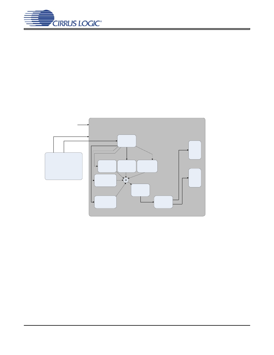
When the Adaptive Power bits are set to 00, the CS42L55 decides which set of rail voltages to send to
the amplifiers based upon the gain and attenuation levels of all active internal processing blocks. In order
to adjust for external analog (line or microphone sources) or digital (DSP) input volume settings, it also
takes into account the settings of the AIN and DIN advisory volume registers. The combined effect of all
volume settings is shown in
If the total gain and attenuation set in the volume control registers would cause the amplifiers to clip a full-
scale signal when operating from the lower set of rail voltages, the control logic instructs the charge pump
to provide the higher set of the two rail voltages (±VCP) to the amplifiers. If the total gain and attenuation
set in the volume control registers would not cause the amplifiers to clip a full-scale signal when operating
from the lower set of rail voltages, the control logic instructs the charge pump to supply the lower set of
rail voltages (±VCP/2) to the amplifiers.
Note:
The A and B channels of each respective volume control must both cross the threshold to trigger
a change in the VCP mode. The control logic also monitors various functions (listed in the table below)
that may affect the total gain and attenuation of the signal applied to the amplifiers.
External DSP
Control Logic
Charge
Pump
PMIX, AMIX
Volume
Setting
Master
Volume
Setting
Headphone or
Line Volume
Setting
Control Port
H
e
ad
phone
Am
pli
fie
r
Li
ne
A
m
p
lif
ie
r
AIN Advisory
Volume Setting
DIN Advisory
Volume Setting
Analog Input Source
I²S Serial Audio Input
Figure 14. Adaptive Mode 00