Switching specifications - control port, Figure 7. i·c control port timing, Figure 7.i²c control port timing – Cirrus Logic CS42L55 User Manual
Page 18: Cs42l55 switching specifications - control port
18
DS773F1
CS42L55
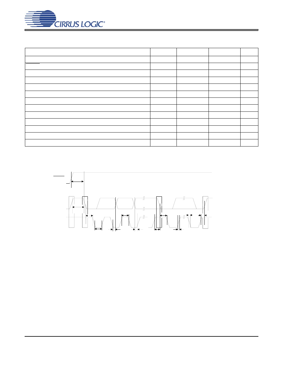
SWITCHING SPECIFICATIONS - CONTROL PORT
Inputs: Logic 0 = GND = AGND, Logic 1 = VL, SDA C
L
= 30 pF.
Notes:
19. Data must be held for sufficient time to bridge the transition time, t
fc
, of SCL.
Parameter Symbol
Min
Max
Unit
SCL Clock Frequency
f
scl
-
100
kHz
RESET Rising Edge to Start
t
irs
500
-
ns
Bus Free Time Between Transmissions
t
buf
4.7
-
µs
Start Condition Hold Time (prior to first clock pulse)
t
hdst
4.0
-
µs
Clock Low time
t
low
4.7
-
µs
Clock High Time
t
high
4.0
-
µs
Setup Time for Repeated Start Condition
t
sust
4.7
-
µs
SDA Hold Time from SCL Falling
t
hdd
0
-
µs
SDA Setup time to SCL Rising
t
sud
250
-
ns
Rise Time of SCL and SDA
t
rc
-
1
µs
Fall Time SCL and SDA
t
fc
-
300
ns
Setup Time for Stop Condition
t
susp
4.7
-
µs
Acknowledge Delay from SCL Falling
t
ack
300
1000
ns
t
buf
t
hdst
t
hdst
t
low
t r
t f
t
hdd
t
high
t sud
t sust
t susp
Stop
Start
Start
Stop
Repeated
SDA
SCL
t
irs
RESET
Figure 7. I²C Control Port Timing