7 dsp header control (address 07h), Table 4. data to dsp, P 20 – Cirrus Logic CDB42438 User Manual
Page 20
CDB42438
20
DS646DB2
5.6.2
DSP DATA ROUTE TO DAC (DSPDATA->DAC)
Default = 1
0 - Enable
1 - Disable
Function:
This bit toggles a control line for the data buffer external to the FPGA to route the DSP Data directly
to the DAC. The inverted signal controls active low buffers internal to the FPGA that routes the FPGA
data to the DAC. Refer to Figure 4 on page 11.
5.6.3
ADC TO AUX SDIN (CS5341->AUX)
Default = 0
0 - Enable
1 - Disable
Function:
This bit toggles a control line for the external data buffer to route the external ADC Data directly to the
AUX_SDIN port. When disabled, the FPGA will route the CS8416 SDOUT to the AUX_SDIN port.
5.7
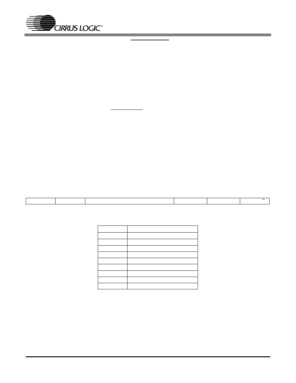
DSP HEADER CONTROL (ADDRESS 07H)
5.7.1
DATA MUX(DATA_MUX[2:0])
Default = 000
Function:
This MUX selects the data lines from the ADC’s and the external ADC. The first selection shown in
Table 4 comes directly from data output line. The last 7 are de-multiplexed from the TDM data stream
(NOTE: in this latter scenario, the data will need to be re-timed from the TDMer’s sub clocks). Refer
to Figure 4 on page 11.
7
6
5
4
3
2
1
0
Reserved
Reserved
DATA_MUX2
DATA_MUX1
DATA_MUX0
Reserved
Reserved
MCLK_M/S
DSP Data Selection
MUX[2:0]
DSP SDIN
000
ADC_SDOUT
001
ADC1 (from ADC_SDOUT)
010
ADC2 (from ADC_SDOUT)
011
ADC3 (from ADC_SDOUT)
100
EXT_ADC (from ADC_SDOUT)
101
ADC1 (from ADC_SDOUT)
110
ADC2 (from ADC_SDOUT)
111
ADC3 (from ADC_SDOUT)
Table 4. Data to DSP