11 overpower protection, 12 open / short loop protection, 13 internal overtemperature protection – Cirrus Logic CS1601H User Manual
Page 13: 14 standby (stby) function, Cs1601, 12 open/short loop protection
CS1601
DS931F3
13
5.11 Overpower Protection
The CS1601 incorporates an internal overpower protection
(OPP) algorithm that provides protection from overload
conditions. This algorithm uses the condition that output
power is a function of the boost inductor (see section
Output Power and PFC Boost Inductor
Under moderate overload, V
link
may droop up to 10% while
maintaining rated power and PFC. Further increasing the load
current causes V
link
to drop below the startup threshold
(~360V). Below this threshold, the circuit switches the
operating mode to startup with more power available to raise
V
link
. As V
link
reaches its nominal value, startup mode is
canceled and power is now limited to the rated value. If the
overload is still present, this cycle will repeat.
If a sustained overload, or a repeated cycle of overload
events, is detected for greater than 112 ms, the CS1601 shuts
down for 2.5 seconds and then attempts to restart.
5.12 Open/Short Loop Protection
If the PFC output sense resistor, R
IFB
, fails (open or short to
GND), the measured output voltage decreases at a slew rate of
about 2 V/
s, which is determined by the ADC sampling rate.
The IC stops the gate drive when the measured output voltage is
lower than the measured line voltage. The IC resumes gate drive
switching when the current into the IFB pin becomes larger than
or equal to the current into the IAC pin, and V
link
is greater than
the peak of the line voltage (V
rect(pk)
). The maximum response
time of open/short loop protection for R
IFB
is about 150
s.
If the PFC input sense resistor R
IAC
fails (open or short to GND),
the current reference signal supplied to the IC on pin IAC falls to
zero.
5.13 Internal Overtemperature Protection
An internal thermal sensor triggers a shutdown when the
temperature exceeds 135°C (nominal) on the silicon. The
sensor sends a signal to the core that supplies current to all
internal digital logic, cutting off power from them. Once the
temperature of the IC has dropped by 9°C (nominal), the
sensor resets, allowing power to the logic.
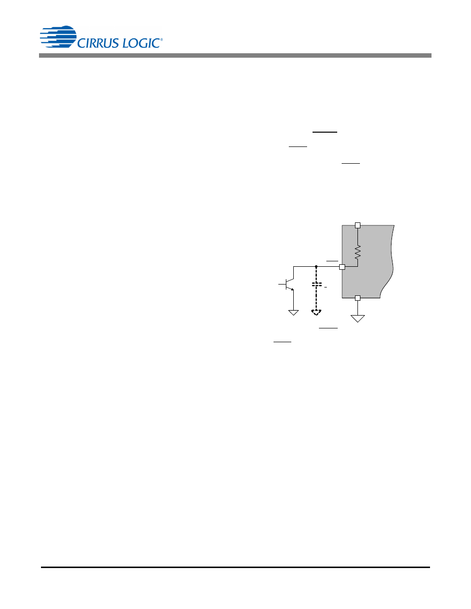
5.14 Standby (STBY) Function
The standby (STBY) pin provides a means by which an
external signal can cause the CS1601 to enter a non-
operating, low-power state. The STBY input is intended to be
driven by an open-collector/open-drain device. Internal to the
pin, there is a pull-up resistor connected to the V
DD
pin, as
shown in Figure 22. Since the pull-up resistor has a high
impedance, a filter capacitor (up to 1000pF) may be required
on this pin.
Figure 22. STBY Pin Connection
When the STBY pin is not used, it is recommended that the pin
be tied to V
DD
(pulled high).
<1 nF
600k
See Text
VDD
STBY
GND
CS1601
8
6
2