8 brownout protection, 9 overvoltage protection, 10 overcurrent protection – Cirrus Logic CS1601H User Manual
Page 12: Cs1601
CS1601
12
DS931F3
table below depicts approximate values for R3 and R4 for a
range of boost-to-auxiliary inductor turns ratio, N.
Table 1. Aux Inductor Turns Ratio vs. R3 and R4
Resistors R3 and R4 were calculated using V
link =
460V and
C
p
= 10pF.
Equation 6 is used to calculate the cut-off frequency defined
by the RC circuit at the ZCD pin.
where:
f
c
The cut-off frequency, f
c
, needs to be 10x the ringing
frequency.
C
p
Capacitance at the ZCD pin
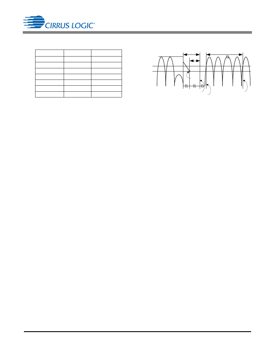
5.8 Brownout Protection
The CS1601 brownout detection circuit monitors the peak of
the V
rect
input voltage and disables the PWM switching when
it drops below a predetermined threshold. Hysteresis and
minimum detection time are provided to avoid brownout
detection during short input transients. When brownout is
detected, the CS1601 enters standby mode. On recovery from
brownout, it re-enters normal operating mode.
Current I
AC
is proportional to the AC input voltage V
rect
, where
V
rect
= R
IAC
xI
AC
and R
IAC
= R1+R2 (see
page 11). The digitized current applied to the IAC pin is
monitored by the brownout protection algorithm. When V
rect
drops below the brownout detection threshold, the CS1601
triggers a timer. The IC asserts the brownout protection and
stops the gate-drive switching only if the timer exceeds 56ms.
This is the equivalent of 7 rectified line cycles at 60Hz.
During the brownout state, the device continues monitoring
the input line voltage. The device exits the brownout state
when I
AC
exceeds the brownout upper threshold for at least
56ms. Typical values for the lower (I
BP(lower)
) and upper
(I
BP(upper)
) brownout thresholds are 31.6
A and 39.6A,
respectively.
The overpower protection may activate prior to brownout
protection, depending on the load.
Figure 21. Brownout Sequence
The maximum response time of the brownout protection
feature occurs at light-load conditions. It is calculated by
Equation 7.
where:
V
BP(th)
Brownout threshold voltage, V
BP(th) =
I
BP(lower)
xR
IAC
5.9 Overvoltage Protection
The overvoltage protection (OVP) will trigger immediately and
stop the gate drive when the current into the IFB pin (I
OVP
)
exceeds 105% of the reference current (I
ref
) value. The IC
resumes gate drive switching when the measured current at IFB
drops below I
OVP
– I
OVP(Hy)
. Equation 8 is used to calculate the
OVP threshold (V
OVP
).
5.10 Overcurrent Protection
To limit boost inductor current through the FET and to prevent
boost inductor saturation conditions, the CS1601 incorporates
a cycle-by-cycle peak inductor current limit circuit using an
external shunt resistor to ‘sense’ the FET source current
accurately. The overcurrent protection (OCP) circuit is
designed to monitor the current when the active switch is
turned on. The OCP circuit is enabled after the leading-edge
blanking time (t
LEB
). The shunt voltage is compared to a
reference voltage, V
cs(t h)
, to determine whether an
overcurrent condition exists. The OCP circuit triggers
immediately, allowing the OCP algorithm to turn off the gate
driver.
The overcurrent protection circuit is also designed to monitor
for a catastrophic overcurrent occurrence by sensing sudden
and abnormal operating currents. A second OCP threshold,
V
cs(clamp)
, determines whether a severe overcurrent condition
exists. This immediately turns off the gate drive, and the
system enters a restart mode. The CS1601 inhibits all
switching operations for approximately 1.6 ms and then
attempts to restart normal operation.
N
~R3
~R4
9
46k
1.75k
10
42k
1.75k
11
37.5k
1.75k
12
35.5k
1.75k
13
32k
1.75k
14
29.5k
1.75k
15
27.5k
1.75k
f
c
1 2
R3 R4
C
p
=
[Eq.6]
56 ms
56 ms
Start
Timer
Enter Standby
Exit Standby
Upper
Lower
Brownout
Thresholds
Start Timer
T
Brownout
T
Brownout
8 ms
8 ms
5 V
------------ 128 V V
BP th
–
56 ms
+
+
=
[Eq.7]
8
=
8
5
--- 128 94.8
–
56
+
+
117ms
=
V
OVP
R
IFB
I
OVP
V
DD
+
=
[Eq.8]