WIKA CS4L User Manual
Page 8
Operating Instructions Temperature Indicating Controller CS4H / CS4L
V1.1
•
05/2006
- 8 -
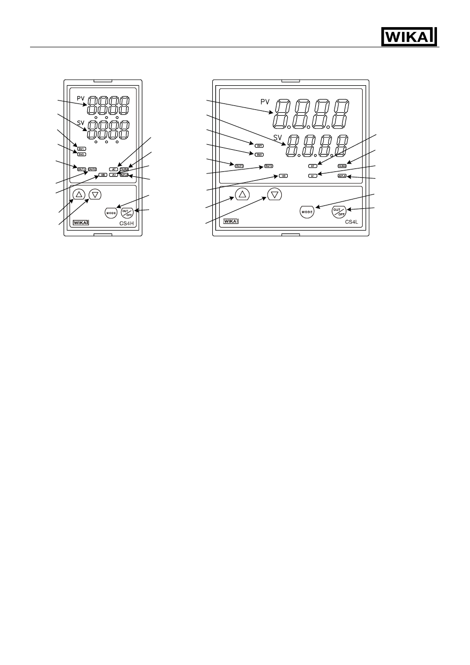
2. Name and functions of the sections
(Fig.
2-1)
Indications:
(1) PV:
PV display
Indicates the process variable (PV) with a red LED.
(2) SV:
SV display
Indicates the setting value (SV) or manipulated variable (MV) with a green LED.
(3) SV1:
Set value 1 indicator
When set value 1 (SV1) is selected, a green LED lights.
(4) SV2:
Set value 2 indicator
When set value 2 (SV2) is selected, a yellow LED lights.
(5) OUT1: Control output 1 (OUT1) indicator
When OUT1 or Heating output is ON, a green LED lights.
(In the case of DC current output type, it blinks in a 0.25 second cycle corresponding
to the output manipulated variable.)
(6) OUT2: Control output 2 (OUT2) indicator
When OUT2 is ON, a yellow LED lights.
(In the case of DC current output type, it blinks in a 0.25 second cycle corresponding
to the output manipulated variable.)
(7) HB:
HB indicator
When Heater burnout alarm output or Sensor burnout alarm output is ON, a red LED lights.
(When Heater burnout Alarm is added, a red LED also lights when the indication is
overscale or underscale)
(8) AT:
Auto-tuning (AT) indicator
When Auto-tuning or Auto-reset is active, a yellow LED blinks.
(9) TX/RX: TX/RX indicator
When serial communication TX (transmitting) is outputted, a yellow LED lights.
(10) A1:
Alarm 1 (A1) indicator
When A1 output is ON, a red LED lights.
(11) A2/LA: Alarm 2 (A2/LA) indicator
When A2 output is ON, a red LED lights.
(1)
(2)
(3)
(4)
(6)
(7)
(5)
(12)
(9)
(8)
(10)
(15)
(11)
(13)
(14)
(12)
(13)
(1)
(2)
(3)
(4)
(6)
(7)
(5)
(9)
(8)
(10)
(15)
(11)
(14)