WIKA CS4L User Manual
Page 43
Operating Instructions Temperature Indicating Controller CS4H / CS4L
V1.1
•
05/2006
- 43 -
Attached functions
[Sensor correction function]
[Setting value lock function]
[Input burnout indication]
• For thermocouple or RTD input, if the input value exceeds the Indication range high limit value, the
PV display blinks “
” and if the input value exceeds Indication range low limit value, the PV
display blinks ”
”.
If the input value exceeds the Control range, OUT1 and OUT2 are turned OFF (for control output
Analogue current signal (4 ... 20 mA), OUT1 low limit value, OUT2 low limit value).
(However, for manual control, it outputs the preset manipulated variable)
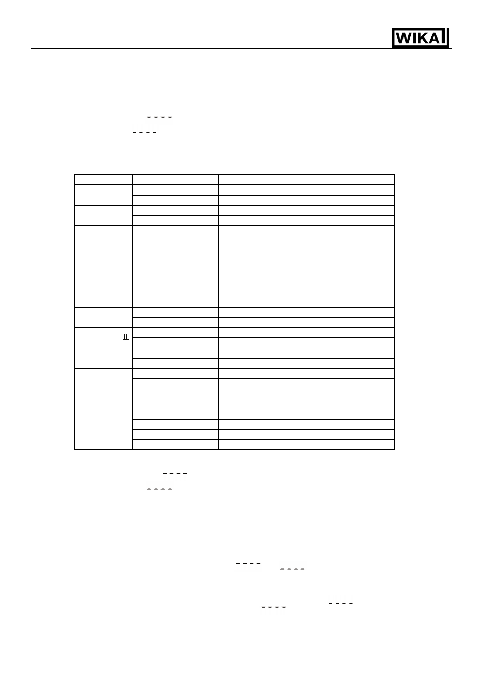
Input
Input range
Indication range
Control range
–199.9 ... 400.0 °C
–199.9 ... 450.0 °C
–205.0 ... 450.0 °C
K,T
–199.9 ... 750.0 °F
–199.9 ... 850.0 °F
–209.0 ... 850.0 °F
–200 ... 1370 °C
–250 ... 1420 °C
–250 ... 1420 °C
K
–320 ... 2500 °F
–370 ... 2550 °F
–370 ... 2550 °F
–200 ... 1000 °C
–250 ... 1050 °C
–250 ... 1050 °C
J
–320 ... 1800 °F
–370 ... 1850 °F
–370 ... 1850 °F
0 ... 1760 °C
–50 ... 1810 °C
–50 ... 1810 °C
R,S
0 ... 3200 °F
–50 ... 3250 °F
–50 ... 3250 °F
0 ... 1820 °C
–50 ... 1870 °C
–50 ... 1870 °C
B
0 ... 3300 °F
–50 ... 3350 °F
–50 ... 3350 °F
–200 ... 800 °C
–250 ... 850 °C
–250 ... 850 °C
E
–320 ... 1500 °F
–370 ... 1550 °F
–370 ... 1550 °F
–200 ... 1300 °C
–250 ... 1350 °C
–250 ... 1350 °C
N
–320 ... 2300 °F
–370 ... 2350 °F
–370 ... 2350 °F
0 ... 1390 °C
–50 ... 1440 °C
–50 ... 1440 °C
PL-
0 ... 2500 °F
–50 ... 2550 °F
–50 ... 2550 °F
0 ... 2315 °C
–50 ... 2365 °C
–50 ... 2365 °C
C(W/Re5-26)
0 ... 4200 °F
–50 ... 4250 °F
–50 ... 4250 °F
–199.9 ... 850.0 °C
–199.9 ... 900.0 °C
–210.0 ... 900.0 °C
–200 ... 850 °C
–210 ... 900 °C
–210 ... 900 °C
–199.9 ... 999.9 °F
–199.9 ... 999.9 °F
–211.0 ... 1099.9 °F
Pt100
–300 ... 1500 °F
–318 ... 1600 °F
–318 ... 1600 °F
–199.9 ... 500.0 °C
–199.9 ... 550.0 °C
–206.0 ... 550.0 °C
–200 ... 500 °C
–206 ... 550 °C
–206 ... 550 °C
–199.9 ... 900.0 °F
–199.9 ... 999.9 °F
–211.0 ... 999.9 °F
JPt100
–300 ... 900 °F
–312 ... 1000 °F
–312 ... 1000 °F
• For DC current and voltage inputs, if the input value exceeds the Indication range high limit value,
the PV display blinks “
” and if the input value exceeds Indication range low limit value, the
PV display blinks “
”.
If the input value exceeds the Control range, OUT1 and OUT2 are turned ON or OFF which has
been selected in [Output status selection when input burnout] (for control output Analogue current
signal (4 ... 20 mA), OUT1 high or low limit value, OUT2 high or low limit value).
(However, for manual control, it outputs the preset manipulated variable)
Indication range
: [Scaling low limit value – Scaling span x 1 %] to
[Scaling high limit value + Scaling span x 10 %]
However, if the input value exceeds the range –1999 ... 9999,
the PV display blinks “
” or “
”.
Control range
: [Scaling low limit value – Scaling span x 1 %] to
[Scaling high limit value + Scaling span x 10 %]
• DC input burnout: When DC input is burnt out, PV display blinks “
” for 4 ... 20 mA DC
and 1 ... 5 V DC inputs, and “
” for 0 ... 1 V DC input.
For 0 ... 20 mA DC, 0 ... 5 V DC and 0 ... 10 V DC inputs, the PV display
indicates the corresponding value for which 0 mA or 0 V is inputted.