Warning – WIKA CF2S User Manual
Page 36
Operating Instructions Temperature Indicating Controller CF2S
V1.2
•
08/2004 - 36 -
11. Wiring connection
Warning
Turn the power supply to the instrument off before wiring or checking.
Working or touching the terminal with the power switched on may result
in an Electric Shock which could cause severe injury or death.
Moreover, the instrument must be grounded before the power supply to the
instrument is turned on.
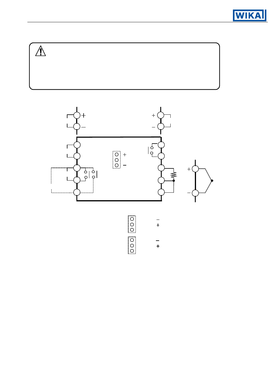
11.1 Terminal arrangement
[Fig. 11.1-1]
A1:
Alarm 1
P. end 1: Pattern end 1
A2:
Alarm 2 [2AS]
P. end 2: Pattern end 2
[2AR]:
Loop break alarm
[2AL]:
Alarm 2 and loop break alarm with common terminals
[CR2], [CR5]: Serial communication [SM2]:
Setting value memory number external selection
• The terminal block of this instrument is designed to be wired from the left side.
The lead wire must be inserted from the left side of the terminal, and fastened with the terminal screw.
• Dotted lines show options, no terminal is equipped if it is not specified.
• If the Alarm 2 (pattern end 2 output) is applied with a combination of the Loop break
alarm output, the output terminal is common.
• Serial communication [CR2, CR5] cannot be applied in combination with the options
[2AS], [2AR], [2AL] and [SM2].
Alarm 2 (A2) is applied, however, it does not involve the alarm output but
provides the functions for indication and communication.
1
4
2
6
7
9
10
5
A1/P.end 1
SM
[Control output]
Relay contact
output
3
8
C, C5
100 to 240Vac
or 24Vac
1
2
24Vdc
A2/P.end 2/LA
RTD
B
B
A
TC
TX (color of wire: Yellow)
RX (color of wire: Blue)
COM (color of wire: Black)
YA ( ) (color of wire: Yellow)
YB ( ) (color of wire: Blue)
COM (color of wire: Black)
RS-485
RS-232
YA ( ) (color of wire: Yellow)
YB ( ) (color of wire: Blue)
COM (color of wire: Black)
6
7
[Control output]
Non-contact
voltage output or
current output
10
8
C2, C5
SM2