WIKA CF2S User Manual
Page 16
Operating Instructions Temperature Indicating Controller CF2S
V1.2
•
08/2004 - 16 -
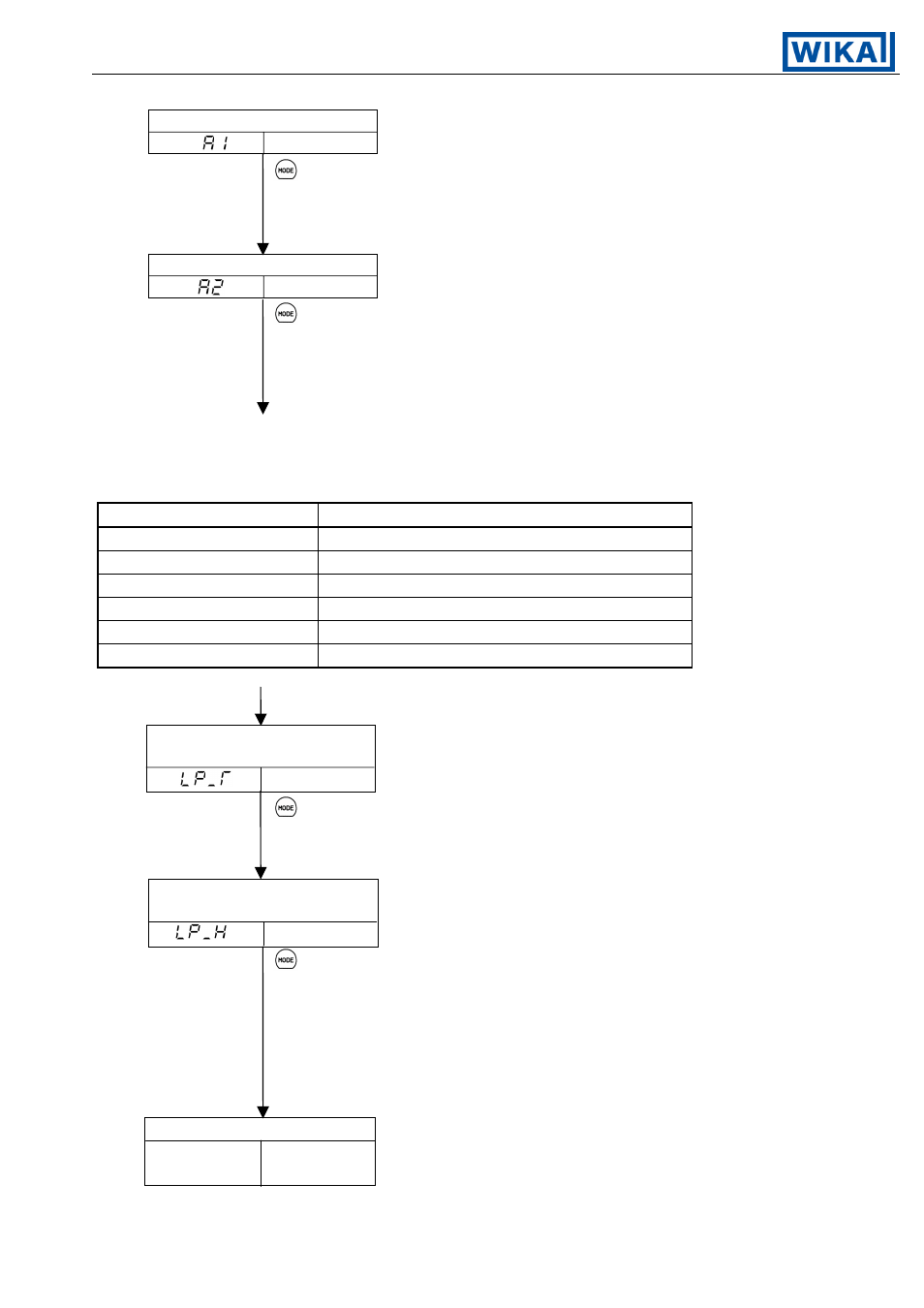
Alarm 1 (A1) setting
Mode to set the action point of the Alarm 1 (A1) output.
Setting value
This item is not displayed if setting the rotary switch
to No. 0 or No. 7 (See page 12.)
Setting range: see [table 4.2-2].
[Factory adjusted as 0°C]
Alarm 2 (A2) setting
Mode to set the action point of the Alarm 2 (A2) output.
Setting value
This item is not displayed if the option [A2] is not
applied or even if it is applied, when setting the
rotary switch to No. 0 or No. 7 (See page 12.)
Setting range: see [table 4.2-2].
[Factory adjusted as 0°C]
Setting range of Alarm 1 and 2
(The setting range is the same when the standby function is added.)
[Table 4.2-2]
Alarm type
Setting range
High limit alarm
–Input span to Input span
Low limit alarm
–Input span to Input span
High/Low limits alarm
1 to Input span
High/Low limit range alarm
1 to Input span
Process high alarm
Input range minimum to Input range maximum
Process low alarm
Input range minimum to Input range maximum
For RTD input, the minimum value of the negative side is –199.9.
Loop break alarm
Mode to set the time for Loop break alarm
time setting
activation assessment.
Setting value Setting range: 0 to 200 minutes
[Factory adjusted as 0 minutes.]
This display is indicated only when the option [AR] or
[AL] is applied.
Loop break alarm
Mode to set the span for Loop Break Alarm
span setting
activation assessment.
Setting value Setting range:
0 to 150°C (Thermocouple, except T and RTD
without a decimal point)
0.0 to 150.0°C (Thermocouple T and RTD
with a decimal point)
[Factory adjusted as 0°C]
This display is indicated only when the option [AR] or
[AL] is applied.
PV/SV display mode
Actual Main setting
Temperature value