9 acquiring the edid, Acquiring the edid, Figure 15: cat 5 pinout – Kramer Electronics TP-126-od User Manual
Page 34: Table 15: cat 5 pinout, See section
Wiring the CAT 5 LINE IN / LINE OUT RJ-45 Connectors
31
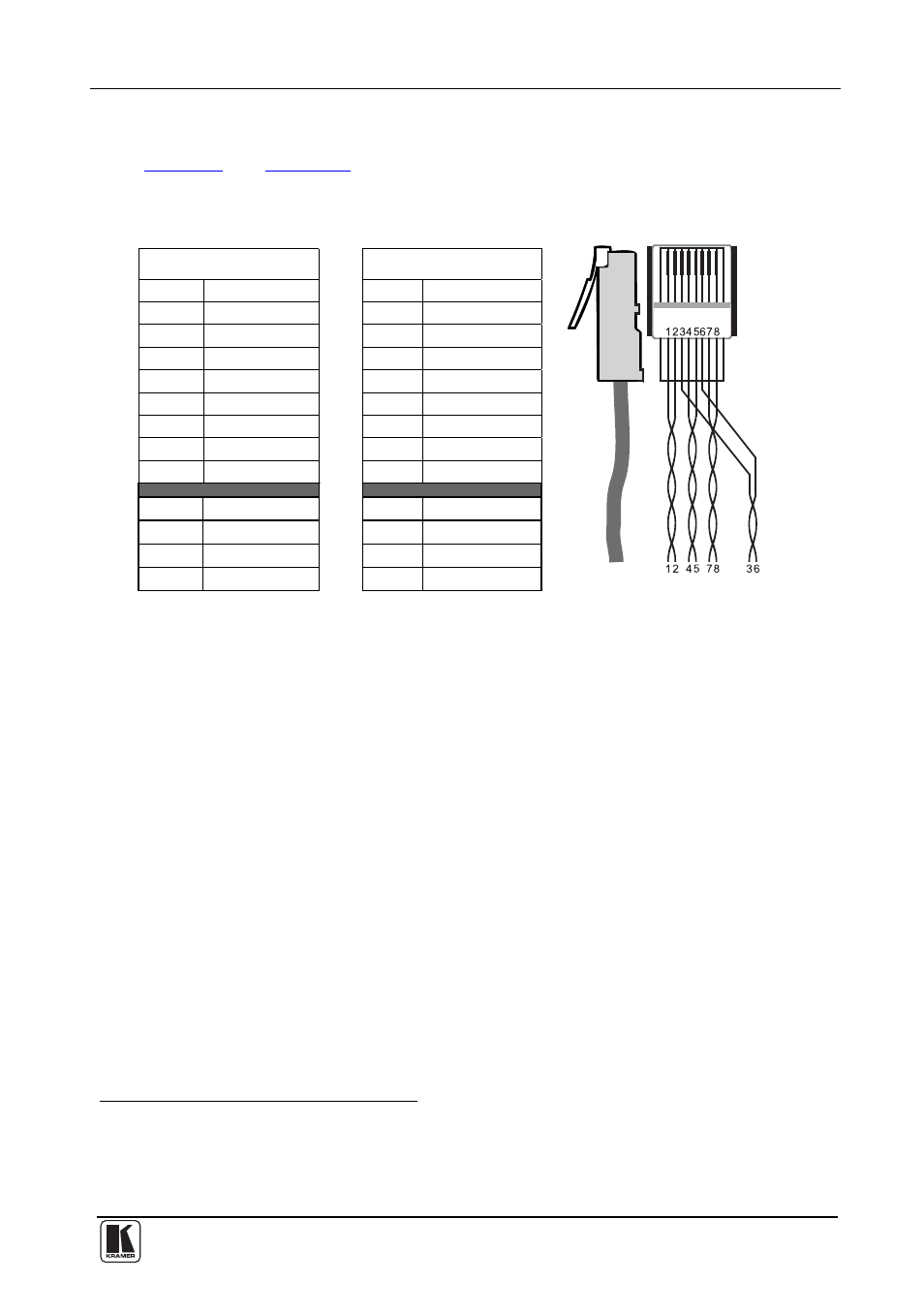
8 Wiring the CAT 5 LINE IN / LINE OUT RJ-45 Connectors
define the UTP CAT 5 PINOUT, using a straight pin
to pin cable with RJ-45 connectors:
Table 15: CAT 5 PINOUT
Figure 15: CAT 5 PINOUT
EIA /TIA 568A
EIA /TIA 568B
PIN
Wire Color
PIN
Wire Color
1
Green / White
1
Orange / White
2 Green
2 Orange
3
Orange / White
3
Green / White
4 Blue
4 Blue
5
Blue / White
5
Blue / White
6 Orange
6 Green
7
Brown / White
7
Brown / White
8 Brown
8 Brown
Pair 1
4 and 5
Pair 1
4 and 5
Pair 2
3 and 6
Pair 2
1 and 2
Pair 3
1 and 2
Pair 3
3 and 6
Pair 4
7 and 8
Pair 4
7 and 8
9 Acquiring the EDID
The transmitter can acquire the EDID information from the display connected
to the transmitter or acquire the default EDID
.
To acquire the display EDID, do the following:
1. Connect the XGA INPUT 15-pin HD connector to the input XGA
connector of the display, using a short cable
.
2. Connect the display power.
3. On the Transmitter, connect the 12V DC power adapter to the power
socket and connect the adapter to the mains electricity.
4. Press the EDID CAPTURE button.
5. Once the EDID STATUS blinks slowly several times, the EDID is
captured.
6. Disconnect the display.
To acquire the default EDID
:
1 This section applies to the PT-110-od, TP-121-od, TP-123-od and TP-125-od)
2 The EDID is carried over pins 12 and 15 of the VGA connector. It is essential that the cable used for capturing the EDID
passes all 15 pins
3 Do not connect the display to the transmitter when acquiring the default EDID