2 your tp-126-od xga / audio / data line receiver, Your tp-126-od xga / audio / data line receiver – Kramer Electronics TP-126-od User Manual
Page 29
KRAMER: SIMPLE CREATIVE TECHNOLOGY
The TP-125-od / TP-126-od Transmitter / Receiver Set
26
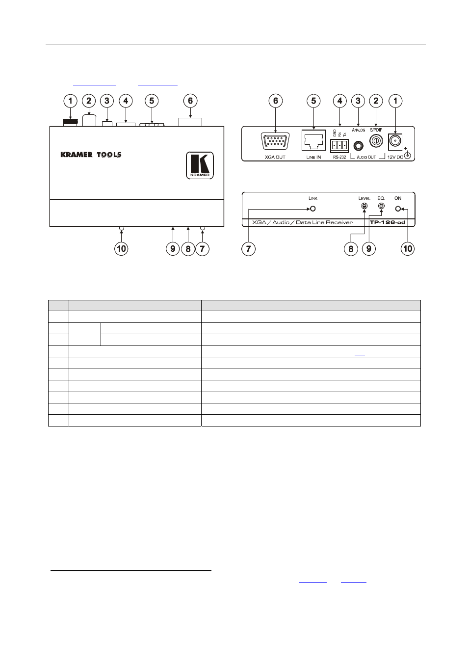
7.2 Your TP-126-od XGA / Audio / Data Line Receiver
and
define the TP-126-od:
Figure 12: TP-126-od XGA / Audio / Data Line Receiver
Table 12: TP-126-od XGA / Audio / Data Line Receiver Features
#
Feature
Function
1
12V DC
+12V DC connector for powering the unit
2 AUDIO
OUT
S/PDIF RCA connector
Connects to the digital audio acceptor
3
ANALOG 3.5mm Mini Jack
Connects to the analog audio acceptor
4
RS-232 Terminal Block Connector
Connects to the controlled unit (see section
5
LINE IN RJ-45 Connector Connects
to
the LINE OUT RJ-45 connector on the TP-125-od
6
XGA OUT 15-pin HD (F) Connector
Connects to the UXGA acceptor
7
LINK LED
Illuminates when receiving the correct input signal
8
LEVEL Trimmer
Adjusts the output signal level
9
EQ.
Trimmer
Adjusts the cable compensation equalization level
10
ON LED
Illuminates when receiving power
1 Using a UTP cable with CAT 5 connectors at both ends (the PINOUT is defined in
Figure 15
and
Table 15
)
2 Degradation and UXGA signal loss can result from using long cables (due to stray capacitance), sometimes leading to a
total loss of sharpness in high-resolution signals