4 connecting a pc or controller to the rs-485 port, Connecting a pc or controller to the rs-485 port, Figure 9: crossed cable rs-232 connection – Kramer Electronics RB-6 User Manual
Page 19: Section
RB-6 - Connecting the RB-6
15
15
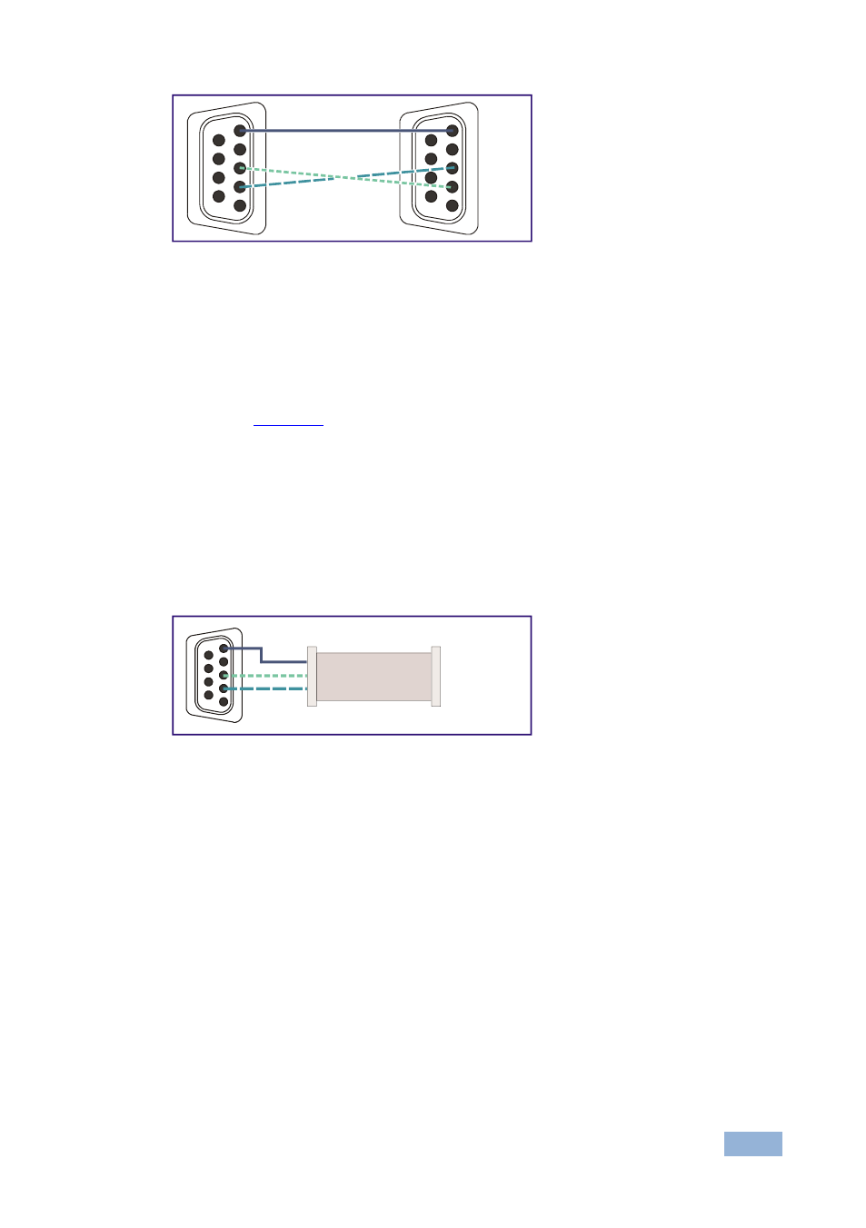
Figure 9: Crossed Cable RS-232 Connection
Hardware flow control is not required for this unit. In the rare case where a
controller requires hardware flow control, short pin 1 to 7 and 8, and pin 4 to 6 on
the controller side.
Method B (
—Connect the RS-232 9-pin D-sub port on the unit via a
straight (flat) cable to the null-modem adapter, and connect the null-modem
adapter to the RS-232 9-pin D-sub port on the PC. The straight cable usually
contains all nine wires for a full connection of the D-sub connector. Because the
null-modem adapter (which already includes the flow control jumpering described
in Method A above) only requires pins 2, 3 and 5 to be connected, you are free to
decide whether to connect only these 3 pins or all 9 pins.
Figure 10: Straight Cable RS-232 Connection with a Null Modem Adapter
6.4
Connecting a PC or Controller to the RS-485 Port
You can operate the RB-6 via the RS-485 port from a distance of up to 1200m
(3900ft) using any device equipped with an RS-485 port (for example, a PC). For
successful communication, you must set the RS-485 machine number and bus
termination.
The first and last device on the RS-485 bus must be terminated. All other devices
must remain unterminated. Move the switch up to terminate and down to
unterminate.
Note: You cannot perform a firmware upgrade using the RS-485 port.
1
2
6
3
7
4
8
5
9
1
2
6
3
7
4
8
5
9
PC
1
2
6
3
7
4
8
5
9
to PC
Null-Modem
Adapter