5 connecting and controlling the vs-81eth – Kramer Electronics VS-81ETH User Manual
Page 7
KRAMER: SIMPLE CREATIVE TECHNOLOGY
Connecting and Controlling the VS-81ETH
4
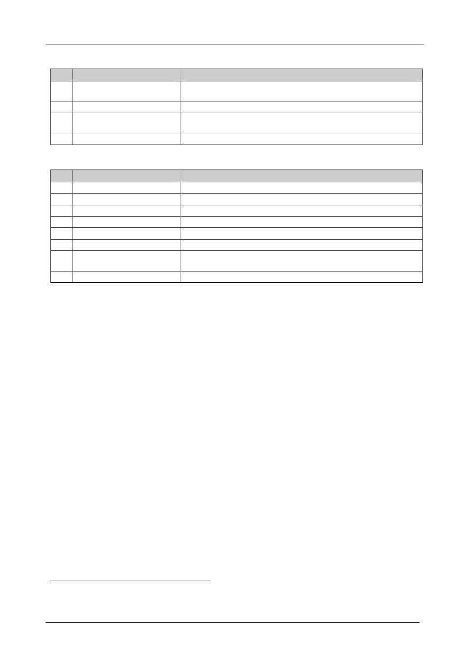
Table 1: Front Panel VS-81ETH 8x1 Universal CAT 5 Switcher Features
#
Feature
Function
1 IR Receiver
The red LED is illuminated when receiving signals from the Infra-red
remote control transmitter
2
POWER
Switch
Illuminated switch for turning the unit ON or OFF
3
IN / OUT SELECTOR
Buttons
Select the input port (1 to 8) to switch to the output port, or select the
output (1 to 8) to which the input is switched
4
PANEL LOCK
Button
Disengages the front panel buttons
Table 2: Rear Panel VS-81ETH 8x1 Universal CAT 5 Switcher Features
#
Feature
Function
5
IN / OUT
CAT5 Connectors
Connect to the digital or analog signal sources/acceptors (from 1 to 8)
6 OUT / IN CAT5 Connector
Connect to the digital or analog signal acceptor/source
7
REMOTE
Terminal Block
Connects to dry contact switches (see section 5.7)
8
RS-485
Terminal Block Port
Pin G is for Ground connection
1
; Pins B (-) and A (+) are for RS-485
9
SETUP
Dipswitches
SETUP
DIPs 1, 2, 3, 4 are for setting the Machine # (see section 5.4)
10
RS-232
DB 9F Port
Connects to the PC or the Remote Controller
11
ETHERNET
Connector
Connects to the PC or other Serial Controller through computer
networking
12 Power Connector with Fuse
AC connector enabling power supply to the unit
5 Connecting and Controlling the VS-81ETH
This section describes how to:
Connect the
VS-81ETH rear panel (see section 5.1)
Connect the
VS-81ETH to a controlling device via RS-232 (see section
5.2), RS-485 (see section 5.3) and/or the Ethernet (see sections 5.5 and
5.6)
Set the dipswitches (see section 5.4)
Connect to a remote-connector (see section 5.7)
Connect several
VS-81ETH machines (see section 5.8)
1
Optional. When using a shielded cable for RS-485, it may be advantageous to connect the shield to ground at one end of the
cable