Kramer Electronics VS-162AVRCA User Manual
Page 21
Installing the Audio-Video Matrix Switcher
17
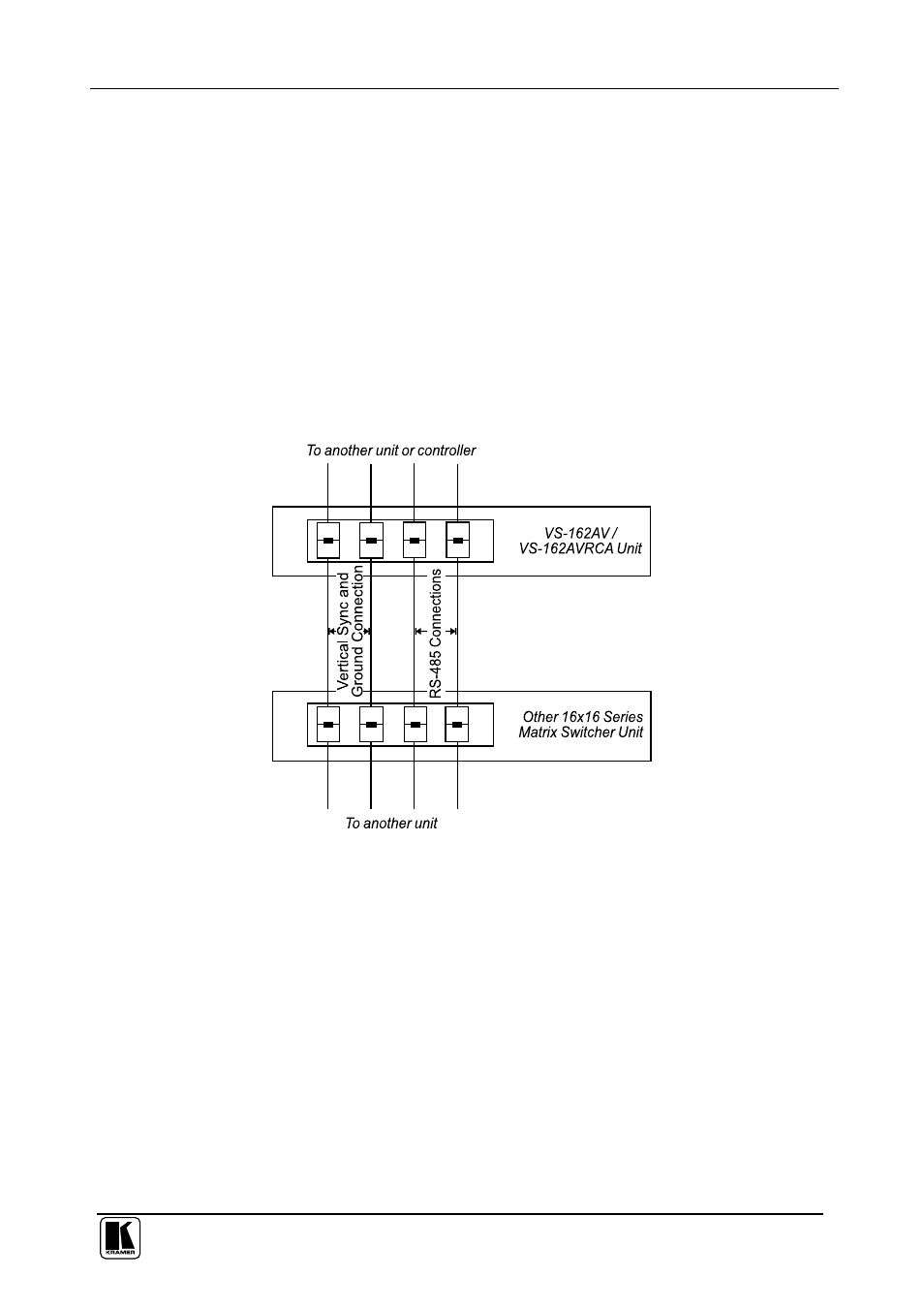
To connect an RS-485 connector on one unit to an RS-485 connector on one
or more other switchers (from the series of 16x16 matrix switchers), as Figure
12 illustrates:
1. Connect the “+” PIN on the first unit to the “+” PIN on the second unit or
other unit
2. Connect the “-” PIN on the first unit to the “-” PIN on the second unit or
other unit
3. If shielded cable is used for an RS-485 connection, connect the shield to
the Ground PIN.
For details about how to configure the vertical sync (if required), refer to
section 6.5 and Figure 17 in section 8.3.1.
Figure 12: Connecting the RS-485 Connectors
Figure 13 illustrates the RS-485 line that connects:
Between the unit, the
VS-1616SDI and the VS-1616AD units
To the PC via a Kramer Tools
VP-43xl Interface Converter (connect the
PC’s DB 9 COM port to the “RS-232 in” DB9F port on the
VP-43xl. Next,
connect the RS-485 port on the
VP-43xl to the RS-485 ports on the unit,
VS-1616SDI and VS-1616AD units by connecting the “A” terminal of the
VP-43xl to the “+” terminals of the switchers, and “B” to “-” terminals)