Figure 2: vp-8x8 user manual rear panel, Figure 3: vp-8x8 underside view – Kramer Electronics VP-8x8 User Manual
Page 9
6
6
VP-8x8 - Overview
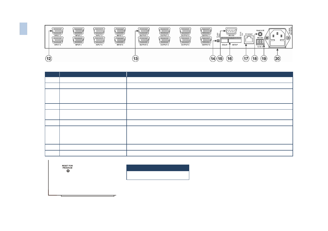
Figure 2: VP-8x8 User Manual Rear Panel
#
Feature
Function
12
15-pin HD INPUT Connectors
Connect to the video sources (from 1 to 8)
13
15-pin HD OUTPUT Connectors
Connect to the output acceptor (from 1 to 8)
14
FLASH PROG Button
Push in for “Program” to upgrade to the latest Kramer firmware, or release for Normal (the
factory default)
The FLASH PROG “Reset” button is located on the underside of the unit
15
RS-232 9-pin D-sub Port
Connects to the PC or the Remote Controller
16
DELAY and SETUP DIP-switches
DIP-switches for setup of the unit (DELAY dips 1, 2, 3 are for setting the delay time; SETUP
dips 1, 2, 3, 4 are for setting machine #; 8 is for RS-485 Termination)
ETHERNET Connector
Connects to the PC or other Serial Controller through computer networking
18
REMOTE IR 3.5mm Mini Jack
Connect to an external IR receiver unit for controlling the machine via an IR remote controller
(instead of using the front panel IR receiver)
Optional. Can be used instead of the front panel (built-in) IR receiver to remotely control the machine (only if
the internal IR connection cable has been installed)
19
RS-485 Terminal Block Port
Pin G is for Ground connection; Pins B (-) and A (+) are for RS-485
20
Power Connector with Fuse
AC connector enabling power supply to the unit
Feature
RESET FOR PROGRAM Button
Figure 3: VP-8x8 Underside View
6
VP
-8
x
8
–
Ov
e
rv
ie
w