Communication protocol – Kramer Electronics VP-84ETH User Manual
Page 37
KRAMER: SIMPLE CREATIVE TECHNOLOGY
Communication Protocol
34
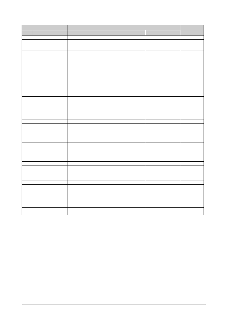
INSTRUCTION
DEFINITION FOR SPECIFIC INSTRUCTION
#
DESCRIPTION
INPUT
OUTPUT
NOTE
0
RESET MACHINE
0
0
1
1
SWITCH VIDEO
Set equal to video input to be switched
Set equal to video
output to be switched
(0=to all the outputs)
2
2
SWITCH AUDIO
Set equal to audio input to be switched
Set equal to audio
output to be switched
(0=to all the outputs)
2
3
STORE STATUS
Set as SETUP #(1-8)
- To store parameters
- to delete setup
2,7
4
RECALL STATUS
Set as SETUP #(1-8)
Don’t care
2,7
5
REQUEST STATUS
OF A VIDEO
OUTPUT
Set as SETUP #(1-8)
Equal to output
number whose status
is read
3,7
6
REQUEST STATUS
OF AN AUDIO
OUTPUT
Set as SETUP #(1-8)
Equal to output
number whose
status is read
3,7
7
VIS SETTING
Don’t care
- for immediate
switching
- for VIS switching
2
8
BREAKAWAY
SETTING
Don’t care
- for audio-follow-
video
- for breakaway
2
9
NOT USED
10
REQUEST VIS
SETTING
Set as SETUP #(1-8)
Don’t care
3,7
11
REQUEST
BREAKAWAY
SETTING
Set as SETUP #(1-8)
Don’t care
3,7
12 to
14
NOT USED
15
REQUEST
WHETHER SETUP
IS DEFINED
Set as SETUP #(1-8)
Don’t care
4
16
ERROR/BUSY
Don’t care
Don’t care
5
17
RESERVED
6
18
RESET MACHINE
0
0
1
19
STORE STATUS
Set as SETUP #(1-8)
0-to store parameters
1-to delete setup
2,7,9
20
RECALL STATUS
Set as SETUP #(1-8)
Don’t care
2,7,10
21 to
56
NOT USED
57
SET AUTO-SAVE
for auto save
0 – no save
Don’t care
8,2
58 to
60
RESERVED
61
IDENTIFY MACHINE 1or 2 – machine name
3 or 4 – version
Don’t care
11
NOTES on the above table:
NOTE 1 - When the master switcher is reset, (e.g. when it is turned on), the reset code is sent to the PC. If this code is sent to
the switchers, it will reset according to the present power-down settings.
NOTE 2 - These are bi-directional definitions. That is, if the switcher receives the code, it performs the instruction, and if the
instruction is performed (due to a keystroke on the front panel), then these codes are sent. For example:
0000 0001
1000 0101
1000 1000
0011
was sent from the PC, then the switcher (machine#3) will switch input 5 to output 8. If the user switched input#1 to output#7
via the front panel keypad, then the switcher will send:
0100 0001
1000 0001
1000 0111
1000 0011
to the PC.
When the PC sends one of the commands in this group to the switcher, then, if the instruction is valid, the switcher replies by
sending to the PC the same four bytes that it sent (except for the first byte, where the DESTINATION bit is set "high").