Figure 2, Vp-4x8, 4x8 vga/uxga matrix switcher rear panel – Kramer Electronics VP-4x8 User Manual
Page 9
6
VP-4x8 - Overview
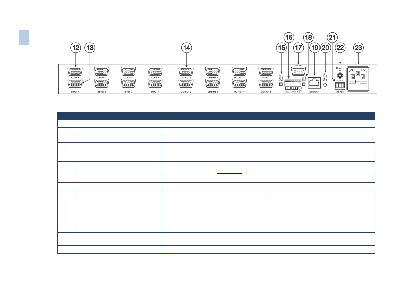
Figure 2: VP-4x8 4x8 VGA/UXGA Matrix Switcher Rear Panel
#
Feature
Function
12
LOOP 15-pin HD (F) Connectors
Connect looped input to output acceptor (1 to 4)
13
INPUT 15-pin HD (F) Connectors
Connect to the video sources (from 1 to 4)
14
OUTPUT 15-pin HD (F) Connectors
Connect to the output acceptor (from 1 to 8)
15
FLASH PROG Button
Push in for “Program” to upgrade to the latest Kramer firmware (see separate firmware upgrade
guide), or release for Normal (the factory default). The FLASH PROG “Reset” button is located
on the underside of the unit
16
DELAY,MACH# and RS-485 TERM
DIP-switches
DIP-switches to set delay (DIPs 1-3), set the machine # (DIPs 4-7) and terminate the RS-485
connection (DIP 8) (see
17
RS-232 9-pin D-sub (F) Port
Connects to the PC or remote controller
18
ETH PROG Button
Push in to upgrade ETH firmware, release for normal operation
19
ETHERNET RJ-45 Connector
Connects to the PC or other serial controller through computer networking
20
ETH Factory Reset Button
Press to reset to factory default definitions:
IP number
− 192.168.1.39
Mask – 255.255.255.0
Gateway – 192.168.1.1
First disconnect the power cord and then
connect it again while pressing the ETH Factory
Reset button. The unit will power up and load its
memory with the factory default definitions
21
RS-485 Terminal Block Port
Pin G is for ground connection; pins B (-) and A (+) are for RS-485
22
REMOTE IR 3.5mm Mini Jack
Connect to an external IR receiver unit for controlling the machine via an IR remote controller
(instead of using the front panel IR receiver)
23
Power Connector with Fuse
AC connector enabling power supply to the unit
6
VP
-4x
8
–
O
v
er
vi
ew