Kramer Electronics VP-4x8 User Manual
Page 29
26
VP-4x8 - Kramer Protocol 2000
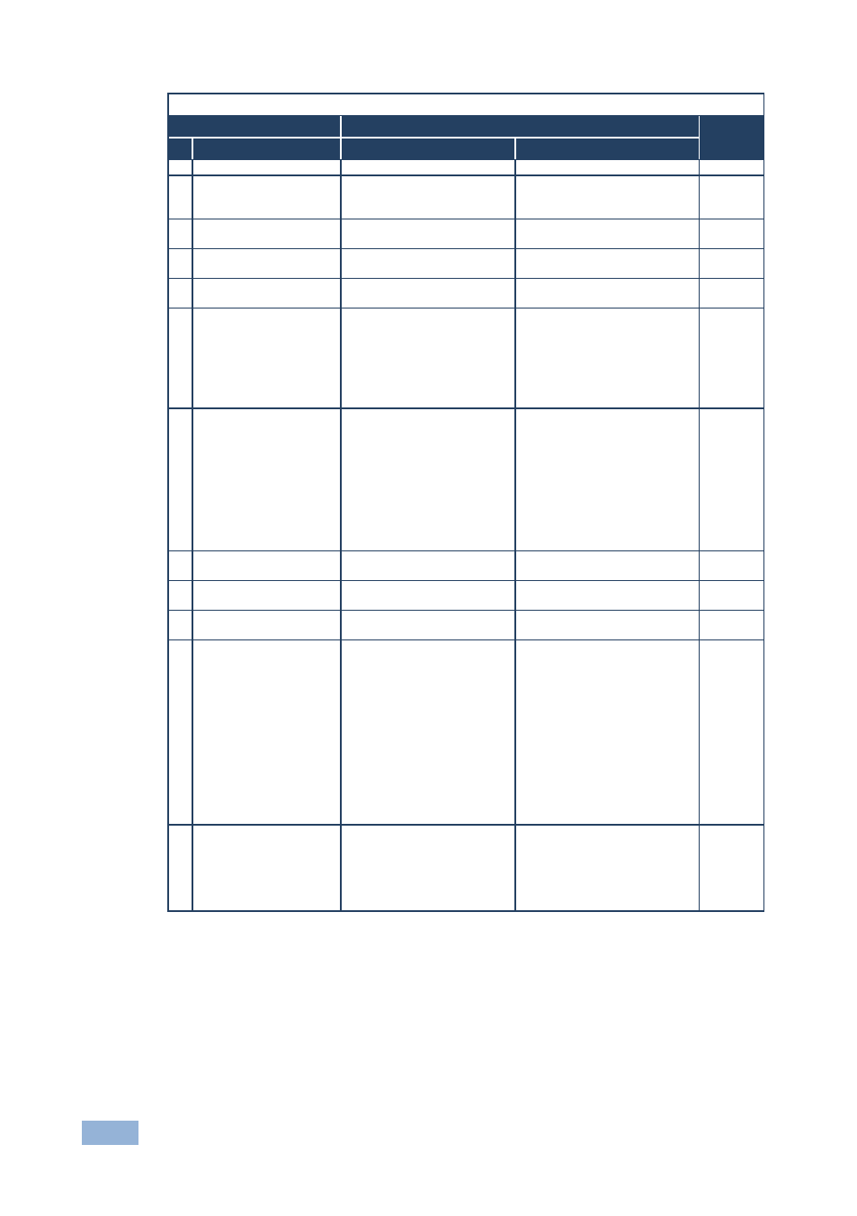
Instruction Codes for Protocol 2000
Instruction
Definition for Specific Instruction
Notes
#
Description
Input
Output
0
RESET VIDEO
0
0
1
1
SWITCH VIDEO
Set equal to video input that is
switched
(0 = disconnect)
Set equal to video output that is
switched
(0 = to all the outputs)
2, 15
3
STORE VIDEO STATUS Set as SETUP #
To store
To delete
2, 3, 15
4
RECALL VIDEO
STATUS
Set as SETUP #
0
2, 3, 15
5
REQUEST STATUS OF
A VIDEO OUTPUT
Set as SETUP #
Equal to output number whose
status is required
4, 3
15 REQUEST WHETHER
SETUP IS DEFINED /
VALID INPUT IS
DETECTED
SETUP #
or
Input #
or
Output #
0 – For checking if setup is
defined
1 – For checking if input is valid
2 – For checking if output is
valid
3 – For checking if EDID output
is valid
8
16 ERROR / BUSY
For invalid / valid input (i.e.
OUTPUT byte = 4 or
OUTPUT byte = 5),
this byte is set as the input #;
For invalid / valid output (i.e.
OUTPUT byte=7 or OUTPUT
byte=8), this byte is set as the
output#
0 – Error
1 – Invalid instruction
2 – Out of range
3 – Machine busy
4 – Invalid input
5 – Valid input
6 – RX buffer overflow
7 – Invalid output
8 – Valid output
9 – Valid EDID
9, 25
30 LOCK FRONT PANEL
0 – Unlock panel
1 – Lock panel
0
2
31 REQUEST WHETHER
PANEL IS LOCKED
0
0
16
57 SET AUTO-SAVE
I3 – No save
I4 – Auto save
0
12, 2
61 IDENTIFY MACHINE
1 – Video machine name
2 – Audio machine name
3 – Video software version
4 – Audio software version
5 – RS-422 controller name
6 – RS-422 controller version
7 – Remote control name
8 – Remote software version
9 – Protocol 2000 revision
10 – Control data machine
name
11 – Control data software
version
For names:
0 – Request first 4 digits
1 – Request first suffix
2 – Request second suffix
3 – Request third suffix
10 – Request first prefix
11 – Request second prefix
12 – Request third prefix
For versions:
0 – main board
or the number of external board
13
62 DEFINE MACHINE
1 – Number of inputs
2 – Number of outputs
3 – Number of setups
1 – For video
2 – For audio
3 – For SDI
4 – For remote panel
5 – For RS-422 controller
6 – For control data
14
NOTES on the above table:
NOTE 1 – When the master switcher is reset, (e.g. when it is turned on), the reset code is sent to the
PC. If this code is sent to a switcher, it resets according to the present power-down settings.