Defining the vp-4x8 4x8 vga/uxga matrix switcher, Figure 1, Vp-4x8 – Kramer Electronics VP-4x8 User Manual
Page 8: 4x8 vga/uxga matrix switcher front panel
VP-4x8 - Overview
5
VP
-4x
8
–
O
v
er
vi
ew
5
3.1
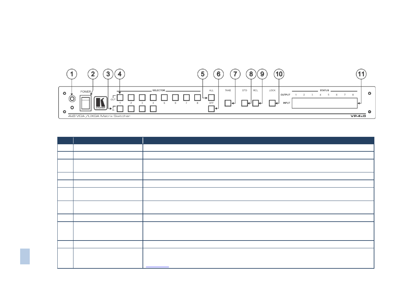
Defining the VP-4x8 4x8 VGA/UXGA Matrix Switcher
This section defines the VP-4x8.
Figure 1: VP-4x8 4x8 VGA/UXGA Matrix Switcher Front Panel
#
Feature
Function
1
IR Receiver
The red LED is illuminated when receiving signals from the infrared remote control transmitter
2
POWER Switch
Illuminated switch for turning the unit ON or OFF
3
IN SELECTOR Buttons
Select the input to switch to the output.
When a signal is detected, the input button illuminates in green
4
OUT SELECTOR Buttons
Select the output to which the input is switched
5
ALL Button
Pressing ALL followed by an INPUT button, connects that input to all outputs
6
OFF Button
Press an OUT SELECTOR button and then an OFF button to disconnect that output from the inputs
Press the ALL button and then the OFF button to disconnect all the outputs
7
TAKE Button
Pressing TAKE toggles the mode between the Confirm mode (in the Confirm mode, the TAKE button
illuminates) and the At Once mode (user confirmation per action is unnecessary)
8
STO (Store) Button
Pressing STO followed by an input/output button stores the current setting
9
RCL (Recall) Button
Pressing the RCL button and the corresponding IN/OUT button recalls a setup from the non-volatile
memory. The stored status flashes. Pressing a different IN/OUT button lets you view another setup.
After making your choice, pressing the RCL button again implements the new status
10
LOCK Button
Disengages the front panel switches
11
STATUS 7-segment Display
Displays the selected input switched to the output (marked above each input)
Also displays the number of IN and OUT ports, the firmware version number, and the MACHINE #. See