RMS Technologies IMDP 23 W/ POLE DAMPING TECHNOLOGY*NEW* User Manual
Page 9
RMS Technologies
Page 9
Version 1.04
IMDP23/IMDEP23 Manual
8/4/2010
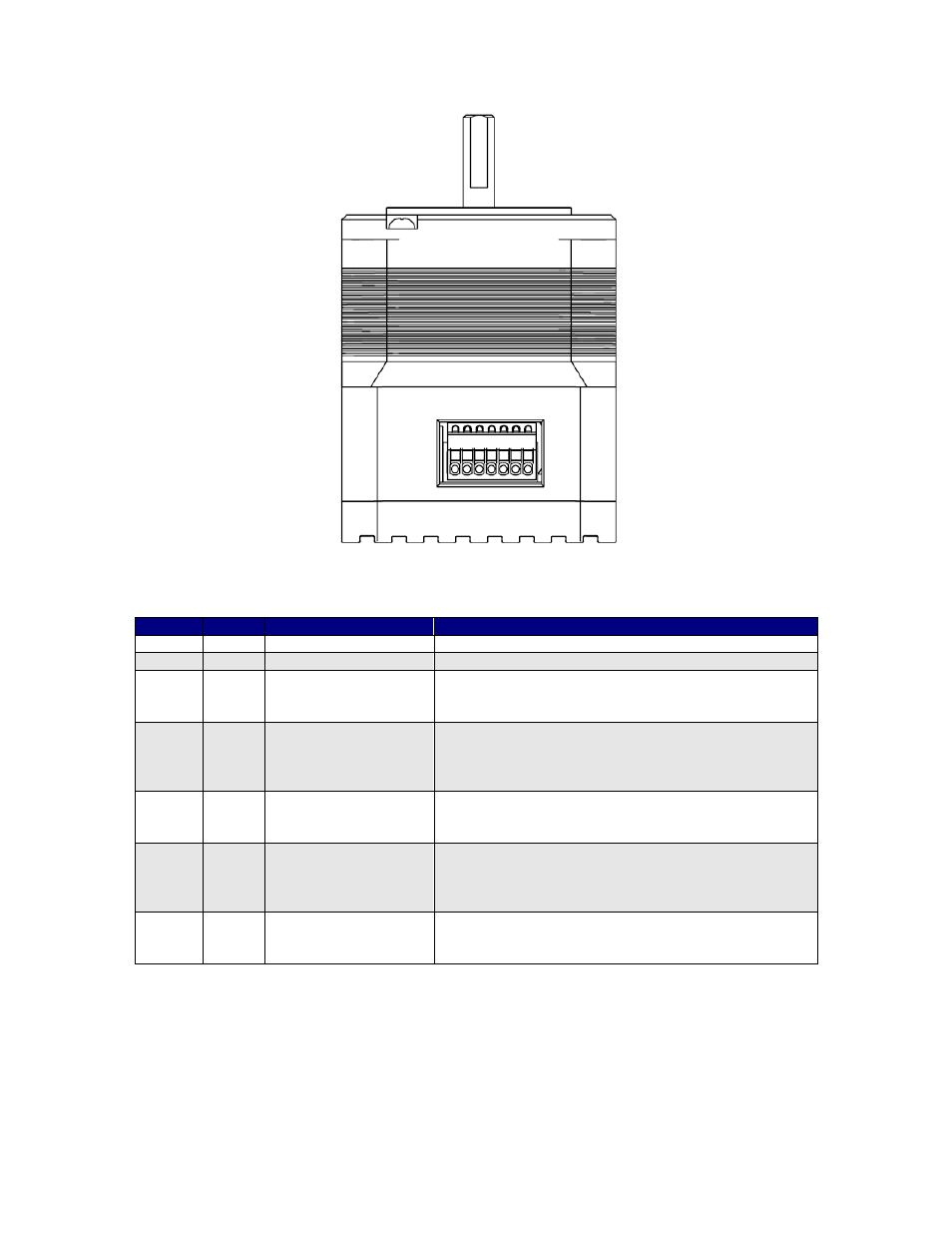
Figure 5: View of IMDP23 Plus connector
Color
Pin
Function
Description
Red
1
POWER +VE
Motor Supply Voltage. +12 to 75 VDC
Black
2
Ground
Power Supply Ground
Orange
3
Enable
Enable/Disables the drive of power. A low signal
will disable the unit. Use the GUI to change this
function such that a high signal disables the unit.
Brown
4
Direction
Direction input. Default connection will rotate
CCW. If this input is low, rotation will be CW. You
can swap this by using the GUI interface and select
“CW” or “CCW” for Direction.
Yellow
5
Step
Step pulse input. The step clock input will receive
a clock pulse input (TTL squarewave, 0 to 5VDC),
where one pulse will move the motor one step.
Blue
6
Internal 5V out
5VDC output. Used to power Pin 7, the opto
reference, if users do not want to use an external
5VDC supply. By using this to power the optos, the
device is no longer optically isolated.
Green
7
Opto reference*
5 VDC is required to power the optocoupler
reference. This device is for sinking operation with
a max input current of 15mAmps.
Table 2: Pin Assignments
*NOTE: If using more than 5VDC to supply the opto reference, pin 7, please see Section 6
for correct resistor values based on the voltage.
The colors listed above are recommended color codes which match the cables that come
with the IMDP23. If you request for lead wires to come directly out of the board, these are
the colors it will follow, where Pin 7 will be a red & white striped wire.
1 2 3 4 5 6 7