RMS Technologies IMDP 23 W/ POLE DAMPING TECHNOLOGY*NEW* User Manual
Page 10
RMS Technologies
Page 10
Version 1.04
IMDP23/IMDEP23 Manual
8/4/2010
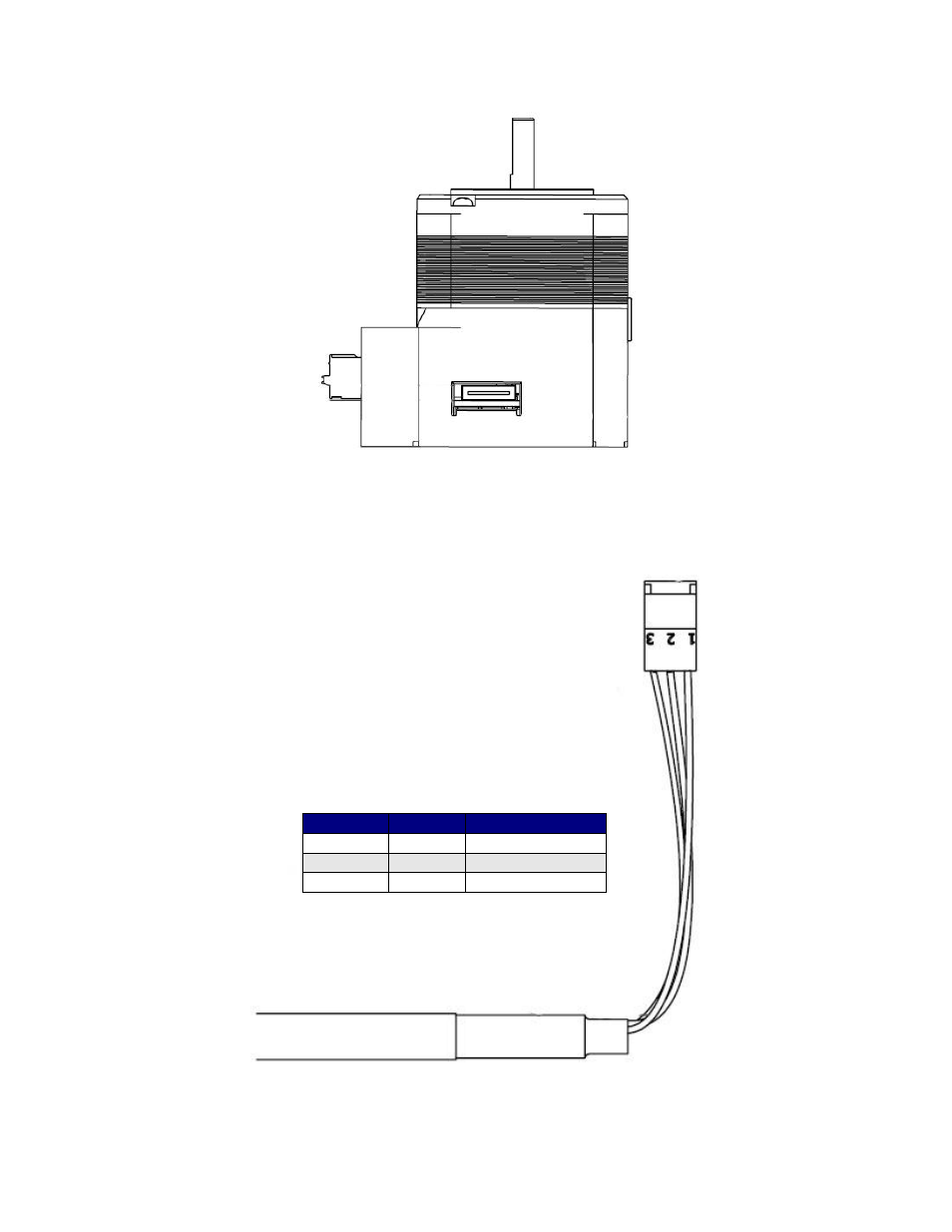
Figure 6: Communication Port View
The above image shows the communication port on the IMDP23. The 18-position cable
plugs into this port. (This cable is sold separately)
Figure 7: Communication Cable
The opposite end of the
communication cable is a 3-pin IDC
(Insulation Displacement Connector).
This connects to either the RS232 or
USB converter card.
Color
Pin #
Function
Black
1
RS485 A (-VE)
Blue
2
Ground
Yellow
3
RS485 B (+VE)
Table 3: Communication Pinouts