Half- stepping current wave form – RMS Technologies IMDP 23 W/ POLE DAMPING TECHNOLOGY*NEW* User Manual
Page 25
RMS Technologies
Page 25
Version 1.04
IMDP23/IMDEP23 Manual
8/4/2010
Amps RMS vs. Amps Peak
Where does the 1.4 times come from? Current is continuously changing when a motor
steps. If the motor is rated for 1.0 A/Ph, it may receive 0 Amps, 1 Amp, 1.4 Amps, or
anything in between if you are microstepping. For ease of explanation, we will look at the
current waveform when we half step, or set the driver/controller to 2x microstepping.
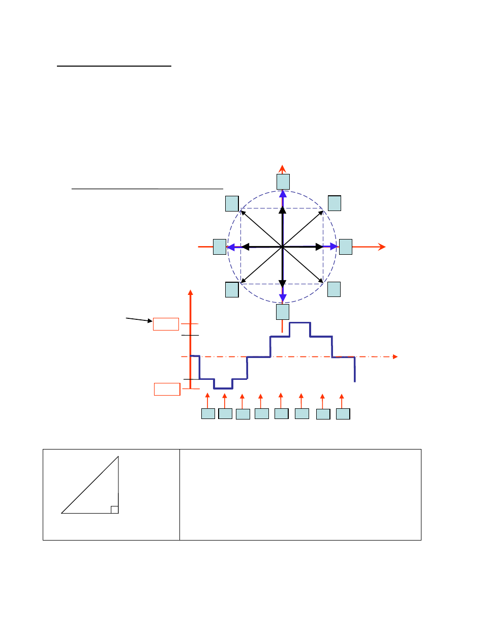
If we take a look at both the A and B phases, and plot on an X-Y chart of when each phase
receives current, and how much it receives, it will look like the chart below. Beginning at
position 1, Phase A receives negative current, and Phase B receives positive current. Let’s
assume it is at coordinate (-1, 1).
The position versus time graph above, plots only the A Phase, following the eight different
steps the motor will make. Current is changing with each position. Recall that a negative in
electronics simply means reverse direction of current flow.
Take a look at position #7. If we were to draw the arrow
at position 7 as the hypotenuse of a triangle, it would
look like the triangle to our left. Recall from geometry a
90°-45°-45° triangle is a 1-1-√2 combination. The √2,
or 1.4 value is also the radius of the dotted circle shown
above. Therefore, during certain steps, Phases A or B will
receive 1.4 Amps of current. But the average, or RMS
current throughout these 8 steps is only 1.0 Amps. RMS
and Amps/Phase is the same meaning.
1.41 AMP
1 AMP
1 AMP
(√2)
1
3
7
5
1
2
3
4
100%
100%
0%
HALF- STEPPING
Current Wave Form
PHASE A
Current
POSITION
PHASE B
PHASE A
2
4
8
6
5
6
7
8
141%
141%
time
Peak current
(1.4 times Amps/Ph)
Average, or RMS
Is only 1 Amp/Ph