Onnecting the, Imdp23, To your – RMS Technologies IMDP 23 W/ POLE DAMPING TECHNOLOGY*NEW* User Manual
Page 13: Rs232, Esistor, Alues for the, Upply
RMS Technologies
Page 13
Version 1.04
IMDP23/IMDEP23 Manual
8/4/2010
Note the COM Port number that was assigned to the converter card device by right-
clicking on “My Computer” and going to:
Hardware Tab Device Manager Ports (COM & LPT) RMS Motion US485
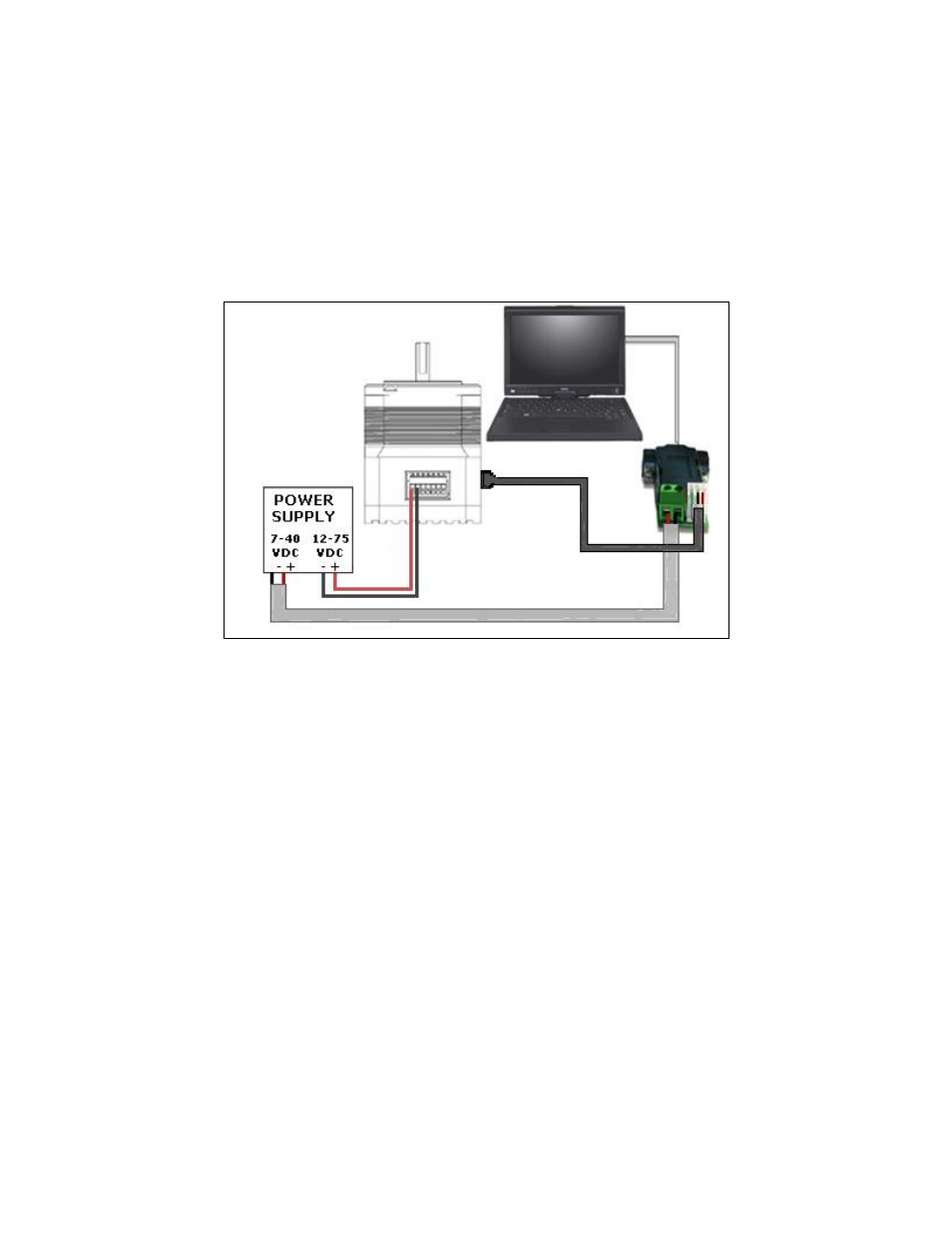
Connecting the IMDP23 to your PC via RS232
Follow the connection schematic shown below if using the RS485-RS232 Converter card.
Figure 13: Connection of Silverpak to RS232 card, PC & Power Supply
Resistor Values for the Opto Supply
The optocouplers must be powered by an external power supply to maintain isolation. The
Opto Supply for the optocouplers can be between +5 to 24 VDC with respect to the signal
input. It is recommended to use a +5 VDC Opto Supply in order to limit the current going
into the optocouplers to 10 mA. However, if the supply is greater than +5 VDC then a
resistor must be connected in series with each signal line to maintain 10 mA of current
running through the optocouplers (step, direction, and disable lines). Do NOT provide
more than 15 mA or damage may occur to the driver.
The following page contains images of resistors and how to connect.