Connection specifications – RMS Technologies IMDP 23 W/ POLE DAMPING TECHNOLOGY*NEW* User Manual
Page 11
RMS Technologies
Page 11
Version 1.04
IMDP23/IMDEP23 Manual
8/4/2010
6
CONNECTION SPECIFICATIONS
In order to properly connect your new IMDP23 Plus unit, first determine which Designer’s
Kit you’ve purchased.
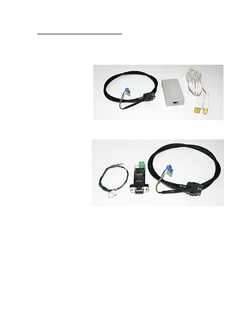
If you purchased a USB485 Designer’s Kit (RMS p/n KIT-USB-02), then you should have
received the following items:
- A black 18-position
cable with 3-pin
connector on other end
(p/n 090-00216)
- USB to RS485 converter
card
- A USB cable (6 feet
long)
Figure 8: USB Kit
If you purchased a RS232-485 Designer’s Kit (RMS p/n KIT-RS232-02), then you should
have received the following items:
- An extra 3-pin cable
- An RS232 to 485
converter card
- A black 18-position
header cable with 3-pin
connector on other end
(p/n 090-00216)
Figure 9: RS232 Kit
Note that the 18-position cable (090-00216) can be purchased separately.
Below are several options for connecting the IMDP23 unit to your controller device.
WARNING!
DO NOT DISCONNECT POWER FROM THE IMDP23 UNIT WHILE POWER IS
STILL BEING SUPPLIED. THIS MAY CAUSE DAMAGE TO THE INTERNAL DRIVER BOARD.
WARNING!
If you do not have a +5 VDC Power Source, use a Resistor in series to limit
the current of the opto isolators. See page 14 for Resistor values. If the current exceeds
15 mA, the opto couplers cease to function.