Connection schematics – RMS Technologies IMDP 23 W/ POLE DAMPING TECHNOLOGY*NEW* User Manual
Page 19
RMS Technologies
Page 19
Version 1.04
IMDP23/IMDEP23 Manual
8/4/2010
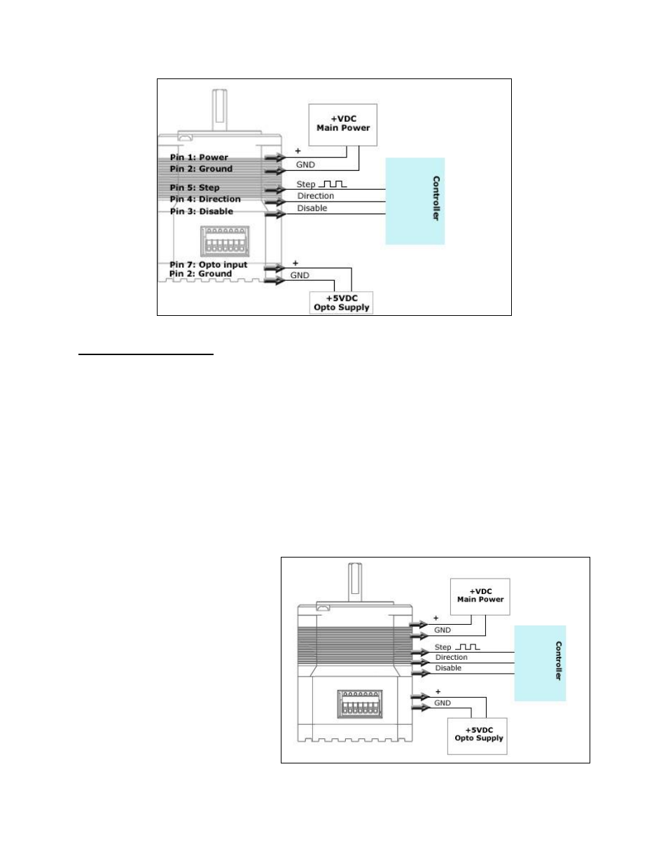
Figure 20: Connection Schematic – Connecting to a Controller
Connecting the Power
The IMDP23 requires a supply voltage of +12-75 VDC. First, connect the positive end of the
power supply to Power (Pin 1), and then connect the negative of the power supply to the
Ground (Pin 2) on the IMDP23.
WARNING!
Be careful not to reverse the polarity from the power supply to the driver.
Reversing the connection will destroy your driver and void the warranty.
Connection Schematics
Using external 5VDC supply for optos:
If using an external 5VDC supply,
connect the positive (+) terminal
to the Silverpak’s opto supply
input, PIN 7.
If using a signal generator,
connect the 5VDC supply ground
terminal to the negative line of
the generator.
Figure 21: Schematic with 5VDC