Step sensing, 9step sensing – RMS Technologies IMD 34 W/ POLE DAMPING TECHNOLOGY*NEW* User Manual
Page 24
RMS Technologies
Page 24
Version 1.00
IMD34 / IMDE34 User Manual
4/28/2009
9
Step Sensing
The IMD34 is equipped with a parameter setting that allows users to change how it reads
the step pulse input.
Step Sensing
This feature allows for more compatibility with controllers and PLC’s. The IMD34 driver
board receives step pulses from a pulse train, normally a TTL signal, sensing each pulse,
one by one.
The “step sense” feature can choose where to sense each pulse: on the rising edge of the
step or the falling edge (also known as the positive or negative edge).
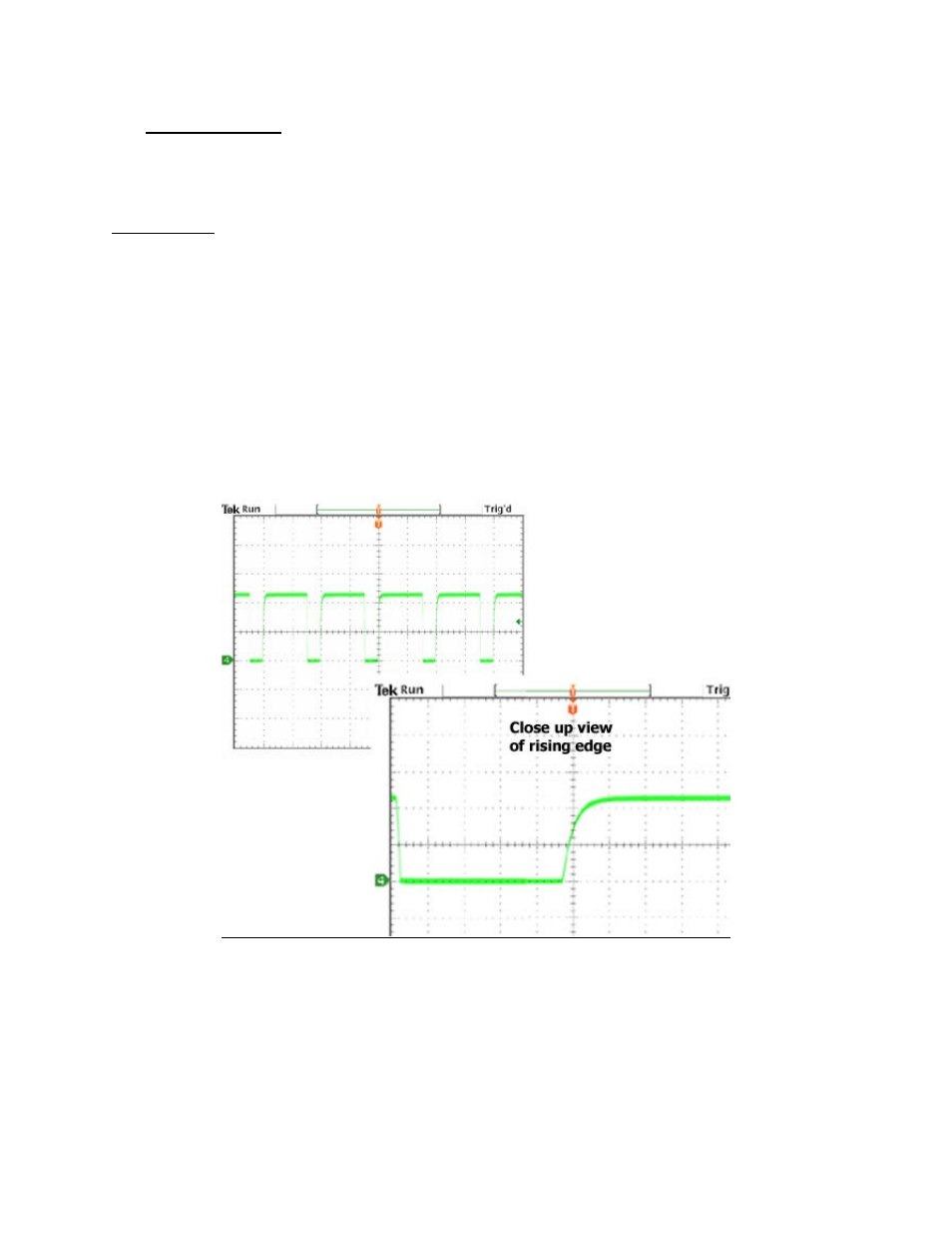
Below depicts a step pulse train waveform where the rising edge is more of a curve. If the
IMD34 is set to read this type of signal on the rising edge, inaccurate steps and unsmooth
motion may occur.
It is best to switch the step sensing to the negative edge, or falling edge. Notice in this
example, the falling edge is a clear signal and a definite difference between high to low.
Figure 24: Example of a bad rising edge waveform