Pin assignments, 6pin assignments – RMS Technologies IMD 34 W/ POLE DAMPING TECHNOLOGY*NEW* User Manual
Page 10
RMS Technologies
Page 10
Version 1.00
IMD34 / IMDE34 User Manual
4/28/2009
6
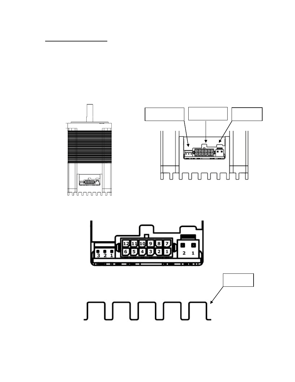
PIN ASSIGNMENTS
A female 12-Pin connector cable provides the control connections for the IMD34 unit. Active
signals are optically isolated. An open collector drive is required to provide pulses for Step,
levels for Direction, and Disable/Enable.
A separate 2-Pin connector needs to receive main power between +24VDC to 75VDC.
All of the signals are optically isolated. The common opto supply can be +5 to 30 VDC with
respect to the signal input; however if the supply is greater than 5 VDC then a resistor must
be inserted in series with each signal line to limit the current to 10 mA.
Figure 7: Image of IMD34
Figure 8: Close-up view of pinouts
Figure 9: Pin numbers for all three connections
3-Pin RS485
communication
12-Pin control
functions
2-Pin Main
Power
Heat sink
P1
P2
P3