Sing external, 5vdc, Supply for optos – RMS Technologies IMD 34 W/ POLE DAMPING TECHNOLOGY*NEW* User Manual
Page 21: Sing, Nternal, Connection schematics
RMS Technologies
Page 21
Version 1.00
IMD34 / IMDE34 User Manual
4/28/2009
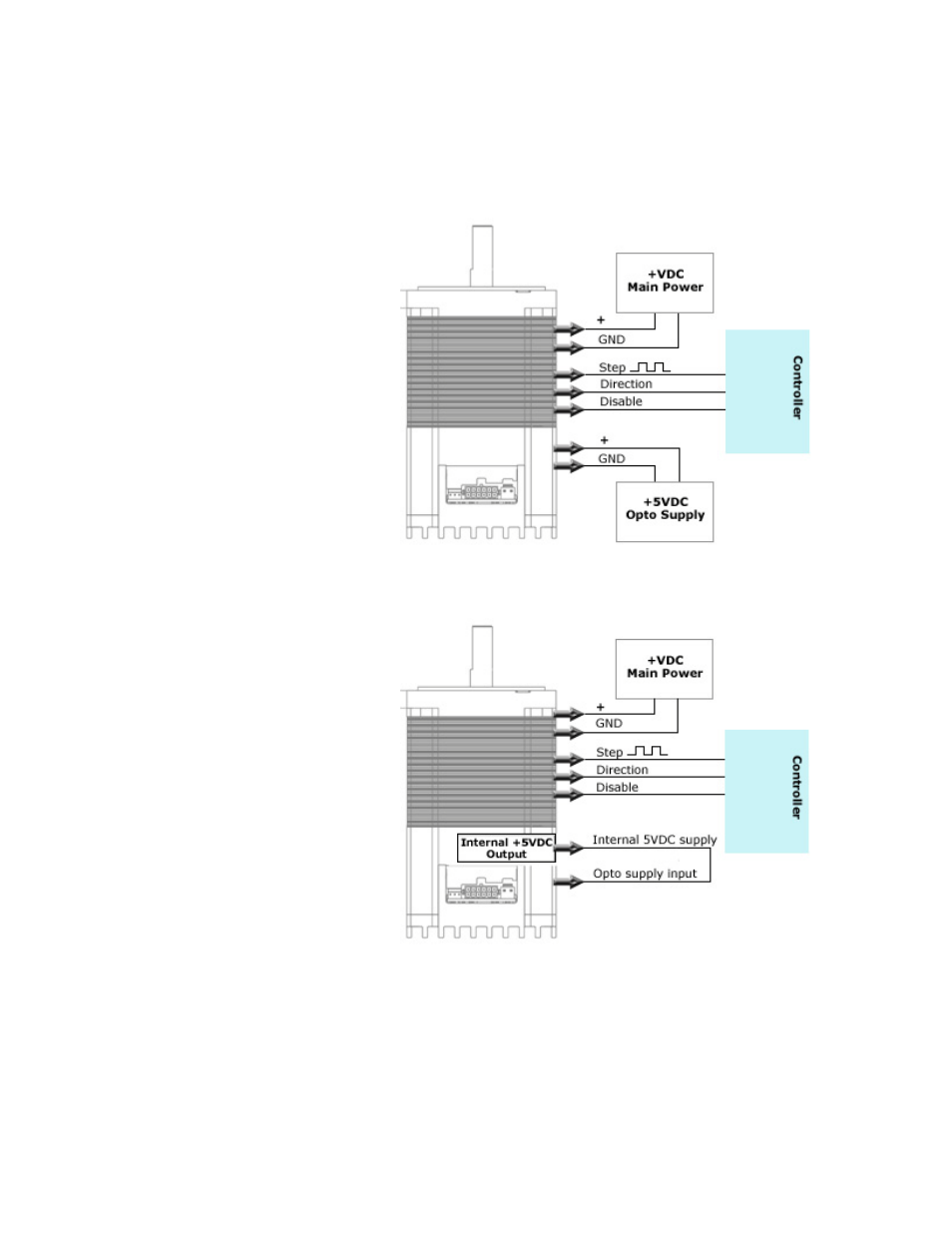
Connection Schematics
Using external 5VDC supply for optos
If using an external 5VDC supply,
connect the positive (+) terminal
to the IMD’s opto supply input,
PIN 2.
If using a signal generator,
connect the 5VDC supply ground
terminal to the negative line of
the generator.
Figure 20: Schematic with 5VDC
Using IMD’s Internal 5VDC supply for optos
If using the internal 5VDC supply,
simply connect PIN 2 to PIN 4.
Be sure to connect step pulse
ground to the IMD’s Ground, PIN
9.
Changing direction and disabling
the drive is achieved by
connecting these two inputs to
PIN 9, ground.
This type of connection no longer
optically isolates the inputs.
Figure 21: Schematic with internal 5VDC