Connection specifications, 8connection specifications – RMS Technologies IMD 34 W/ POLE DAMPING TECHNOLOGY*NEW* User Manual
Page 19
RMS Technologies
Page 19
Version 1.00
IMD34 / IMDE34 User Manual
4/28/2009
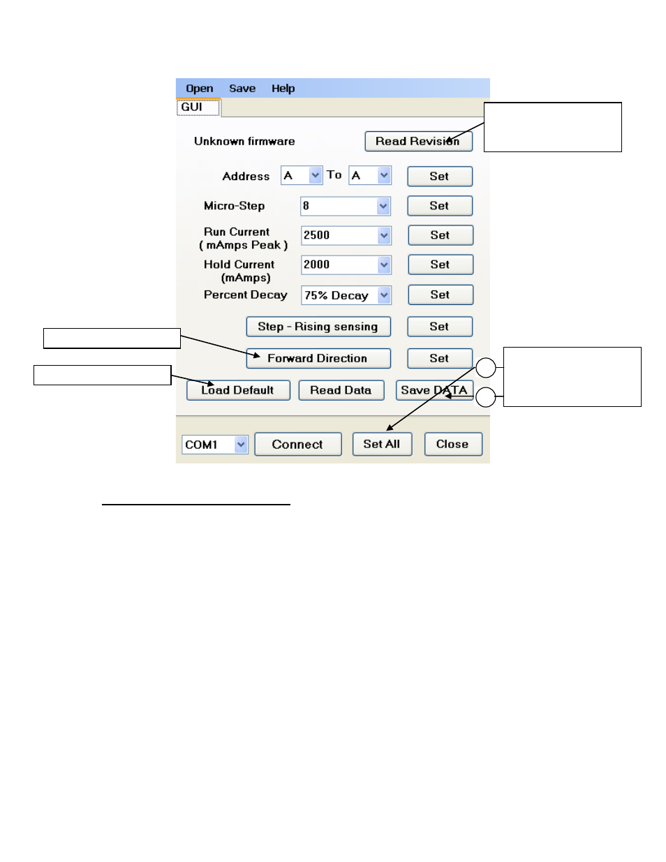
Figure 18: GUI Interface
8
Connection Specifications
List of components needed to rotate the motor:
• +24 to 75 VDC Power Supply
• Additional +5 VDC Volt Power Supply
• Signal Generator
Ensure that the IMD34 is not connected to the Main Power Supply until the following
procedures have been properly carried out.
1. Connect the step pulse generator
Connect Pin 8, step pulse input, to the Positive Terminal of your pulse generator. Then
connect the negative terminal to main ground power.
2. Connect the 5VDC supply
The IMD34 requires a separate 5VDC supply for the optics that turn on the step,
direction, and disable inputs.
1. Set newly changed
settings. 2. Click “Save
DATA” to store values
to EEPROM
2
1
Reads back stored data
Loads default values
1
Click “Set All”
then “Save
DATA” to store
parameters
Reads IMD34 board
firmware version # and
date.