Control pinouts & description (p2), Main power pinouts & description (p1), Communication via rs485 pinouts & description (p3) – RMS Technologies IMD 34 W/ POLE DAMPING TECHNOLOGY*NEW* User Manual
Page 11: Ontrol, Inouts, Escription, Ower, Ommunication via, Rs485
RMS Technologies
Page 11
Version 1.00
IMD34 / IMDE34 User Manual
4/28/2009
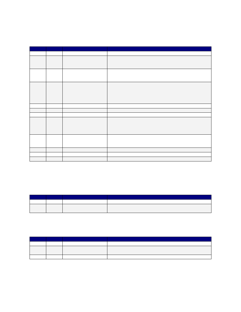
Control Pinouts & Description (P2)
Provides input to the IMD34 driver.
Color
Pin
Function
Description
Black
1
No Connection
This pin is not used
Blue
2
Opto supply input
This pin requires 5VDC to supply the optically isolated
inputs (use resistors if supply is greater than 5V) See
end of Section 6 for details.
White
3
Disable/Enable input
This input is used to enable/disable the driver/motor.
By default, the unit is enabled. Tie to ground in order
to disable unit. When disabled, no power is sent.
Red
4
Internal 5V supply
(output)
The IMD34 has an internal 5V supply. To use this as
your opto supply, jump pins 2 and 4 together. By
doing so, the inputs are no longer optically isolated;
the main power and this 5V supply share the same
circuit.
Green
5
Ground
Same as main ground.
Black
6
Internal use
Internal use
Black
7
No Connection
This pin is not used
Yellow 8
Step Pulse Input
This pin takes in step pulses from a controller, PLC, or
signal generator. The step pulse must be a clean TTL
squarewave signal, max of 10 mAmps current. If
needed, use resistors to limit it to 10mAmps.
Brown 9
Direction Input
This input is used to change the direction of rotation.
By default, it rotates counterclockwise (CCW). By tying
this pin to ground, the motor should rotate CW.
Black
10
No Connection
This pin is not used
Black
11
No Connection
This pin is not used
Black
12
No Connection
This pin is not used
Table 2: Pin Assignments for Controls
Note: All Black wires above are for “No-Connection”
Main Power Pinouts & Description (P1)
Provides main power to the IMD34
Color
Pin
Function
Description
Red
1
PWR +ve
Motor Supply Voltage. +24 to 75 VDC
Black
2
PWR –ve (GND)
The ground or return of the power supply connects
here
Table 3: Pin Assignments for Power
Communication via RS485 Pinouts & Description (P3)
Provides connection to the PC via RS485 in order to set motor parameters.
Color
Pin
Function
Description
Red
1
RS485A (-ve)
RS485 communication (A-)
Black
2
Ground (GND)
Ground connection (must connect to power supply
ground
Green
3
RS485B (+ve)
RS485 communication (B+)
Table 4: Pin Assignments for Communication
In order to set the run current, hold current, step resolution, damping or decay modes, step
and direction of rotation, you must connect to a PC and program these settings. View
section 7 which describes how to configure the settings via the GUI software.