Hbh & hbv, Heat controller oem price list, Model structure – Comfort-Aire HBH Series 1/2 to 5 Ton User Manual
Page 3: Basic unit description
Heat Controller, Inc.
HBH/V COMPACT
IOM Instructions
7 May, 2009
Page 10
HEAT CONTROLLER OEM PRICE LIST
HBH & HBV
Model Structure
HBH & HBV COMPACT Horizontal & Vertical HFC-410a Units
The basic unit price includes sealed heat pump refrigerant circuit and
air handler within cabinetry, lter, and a factory installed hanger kit on
horizontal units.
• Cabinetry - Compact design - galvanized steel construction -
powder coat nish on front access panels - controls access panel
- com pres sor access panels - FPT water con nec tions - high and low
voltage knock outs - 1” (25mm), air lter and lter rack. All vertical
units have a left or right return air option, sizes 015 - 030 have a front
return option. All hor i zon tal units have eld convertible dis charge air
patterns with no extra parts required.
• Standard Controls - CXM Controller, loss of charge switch, high
pressure switch, water coil low temperature cutout, lockout safety
circuit resetable at ther mo stat or dis con nect, LED fault indication,
ve minute anti-short cycle protection, random start, high and low
voltage pro tec tion, con den sate over ow pro tec tion, dry contact for
alarm.
• Compressor - High ef ciency hermetic scroll or rotary, overload
pro tect ed - internally sprung & externally isolated using dual vibration
dampening system for extra quiet operation. Mounting system
incorporates rubber grommet isolation under the compressor and
rubber grommet isolation between the compressor mounting tray and
unit base.
• Reversing Valve - 4-way, pilot operated, solenoid activated in the
cool mode.
• Refrigerant Circuit - Utilizes expansion valve metering device -
copper tubing interconnecting all components - sealed & tested
non-ozone depleting, HFC-410A refrigerant circuit with high & low
side schraeder ports.
• Water to Refrigerant Coil - Tube-in-tube, convoluted copper inner
water tube.
• Refrigerant to Air Coil - Lanced aluminum ns on ri ed copper
tubes.
• Blower Motor - Three-speed PSC direct drive, permanently
lu bri cat ed (Two-speed on 575 volt applications).
• UltraQuiet Option - Compressor incorporates spring mounting
system, 015-060 include compressor discharge muf er, blower
housing is covered with high density noise suppression material.
• Application - Units can be applied in WLHP, GWHP, or GLHP
applications.
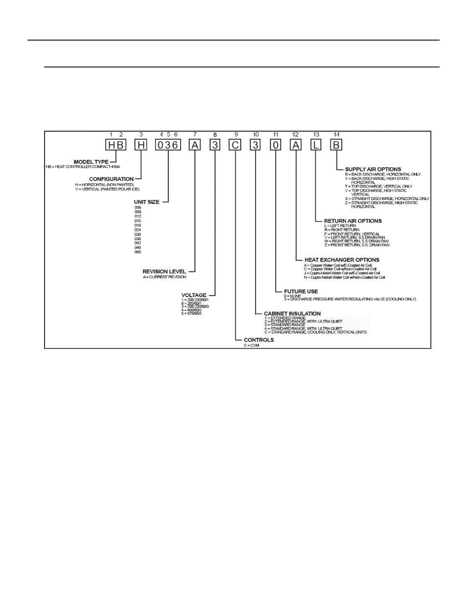
Basic Unit Description:
H B H
A
0 3 6
C
3
3 0 A L B
1 2
3
4 5 6
7
8
9
10
11
12
13
14
HB = HEAT CONTROLLER COMPACT 410A
MODEL TYPE
H = HORIZONTAL (NON PAINTED)
CONFIGURATION
V = VERTICAL (PAINTED POLAR ICE)
UNIT SIZE
018 - 1,8
024 - 1,3,4,8
030 - 1,3,4,8
036 - 1,3,4,8
042 - 1,3,4,5
048 - 1,3,4,5
060 - 1,3,4,5
REVISION LEVEL
A = CURRENT REVISION FOR SIZES 006 - 060
VOLTAGE
C = CXM
CONTROLS
3 = STANDARD RANGE
CABINET INSULATION
0 = NONE
FUTURE USE
A = Copper Water Coil w/E-Coated Air Coil
HEAT EXCHANGER OPTIONS
C = Copper Water Coil w/Non-Coated Air Coil
L = LEFT RETURN
RETURN AIR OPTIONS
R = RIGHT RETURN
F = FRONT RETURN, VERTICAL 009-030
B = BACK DISCHARGE, HORIZONTAL ONLY
SUPPLY AIR OPTIONS
Y = BACK DISCHARGE, HIGH STATIC
HORIZONTAL 018 - 060
T = TOP DISCHARGE, VERTICAL ONLY
V = TOP DISCHARGE, HIGH STATIC
VERTICAL 018 - 060
S = STRAIGHT DISCHARGE, HORIZONTAL ONLY
Z = STRAIGHT DISCHARGE, HIGH STATIC
HORIZONTAL 018 - 060
J = Cupro-Nickel Water Coil w/E-Coated Air Coil
N = Cupro-Nickel Water Coil w/Non-Coated Air Coil
4 = STANDARD RANGE, WITH ULTRA QUIET
015 - 1,8
1 = 208-230/60/1
8 = 265/60/1
3 = 208-230/60/3
4 = 460/60/3
5 = 575/60/3
C = STANDARD RANGE, COOLING ONLY, VERTICAL UNITS
3 = DISCHARGE PRESSURE WATER REGULATING VALVE (COOLING ONLY)
NOT AVAILABLE ON UNIT SIZES 006, 009 AND 012
V = LEFT RETURN, S.S DRAIN PAN
W = RIGHT RETURN, S.S DRAIN PAN
Z = FRONT RETURN, S.S. DRAIN PAN 009-030
}
Voltage Code
Entering Water Temperature Range: 20 - 120°F (-6.7 - 48.9°C)
Vertical Water Source Heat Pump
Sizes 015-060
Horizontal Water Source Heat Pump
Sizes 015-060
006-060
006-060
006
R-410A refrigerant circuit with high & low
•
Cabinetry – Compact design - galvanized steel construction - controls
access panel - compressor access panels - FPT water connections -
high and low voltage knockouts - 1” (25mm), air filter and filter rack. All
vertical units have a left or right return air option, sizes 006-030 have a
front return option. All horizontal units have field convertible discharge air
patterns with extra parts required.