Cxm pcb, Caution, Electrical - low voltage wiring – Comfort-Aire HBH Series 1/2 to 5 Ton User Manual
Page 25: Water valve wiring
Heat Controller, Inc.
HBH/V COMPACT
IOM Instructions
Figure 18: FP1 Limit Setting
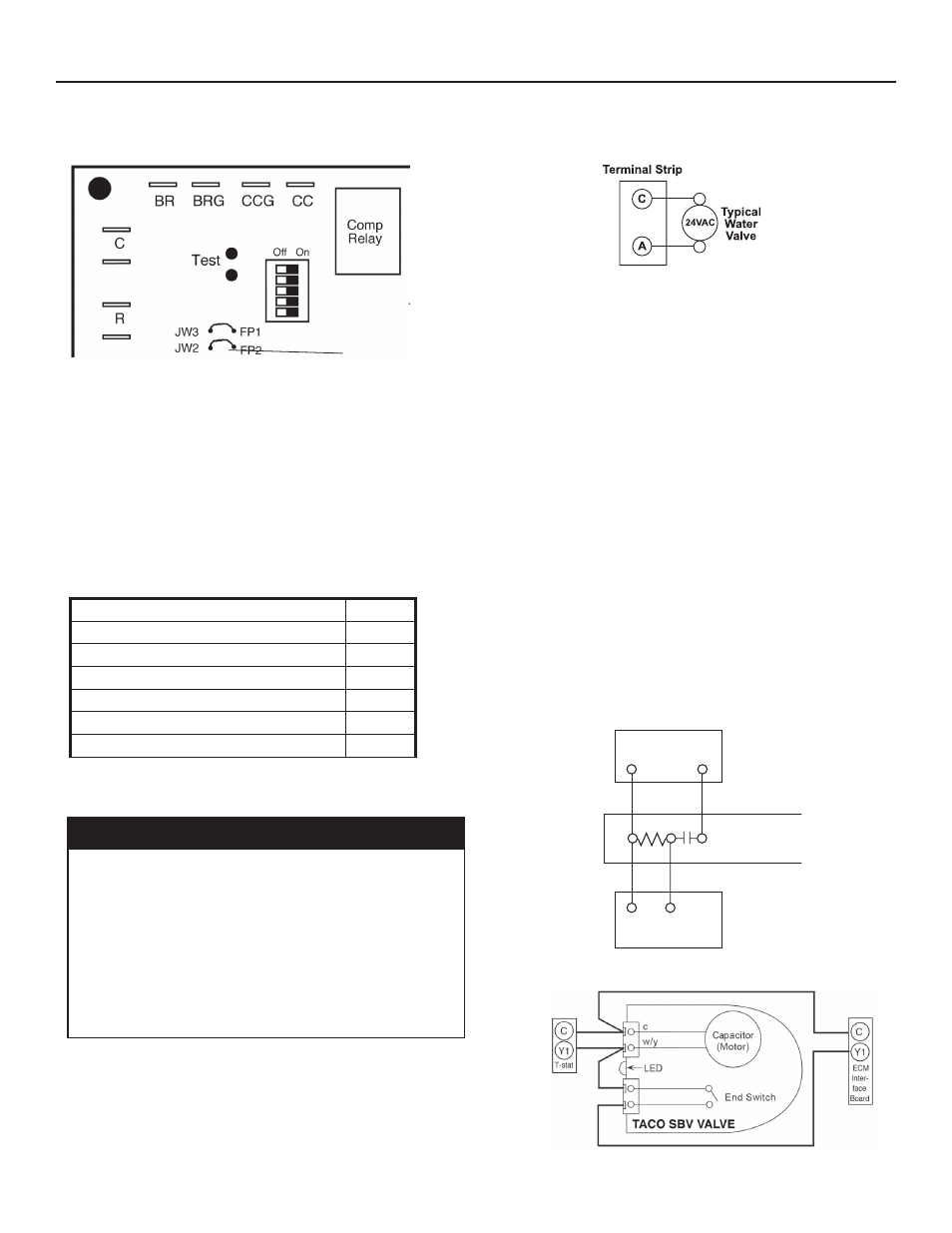
CXM PCB
JW3-FP1
jumper should
be clipped for
low temperature
operation
Accessory Connections
A terminal paralleling the compressor contactor coil
has been provided on the CXM control. Terminal “A”
is designed to control accessory devices, such as
water valves. Note: This terminal should be used only
with 24 Volt signals and not line voltage. Terminal
“A” is energized with the compressor contactor.
See Figure 19 or the specific unit wiring diagram for
details.
Figure 19: Accessory Wiring
Water Solenoid Valves
An external solenoid valve(s) should be used on ground
water installations to shut off flow to the unit when the
compressor is not operating. A slow closing valve may be
required to help reduce water hammer. Figure 19 shows
typical wiring for a 24VAC external solenoid valve. Figures
20 and 21 illustrate typical slow closing water control valve
wiring for Taco 500 series and Taco ESP series valves.
Slow closing valves take approximately 60 seconds to
open (very little water will flow before 45 seconds). Once
fully open, an end switch allows the compressor to be
energized. Only relay or triac based electronic thermostats
should be used with slow closing valves. When wired as
shown, the slow closing valve will operate properly with
the following notations:
1. The valve will remain open during a unit lockout.
2. The valve will draw approximately 25-35 VA through
the “Y” signal of the thermostat.
Note: This valve can overheat the anticipator of an
electromechanical thermostat. Therefore, only relay or
triac based thermostats should be used.
Low Voltage VA Ratings
Component
VA
Typical Blower Relay
6 - 7
Typical Reversing Valve Solenoid
4 - 6
30A Compressor Contactor
6 - 9
Subtotal
16 - 22
+ CXM board (5 - 9 VA)*
21 - 31
Remaing VA for Accessories
19 - 29
*Standard transformer for CXM board is 50VA.
Electrical - Low Voltage Wiring
Figure 20: Taco 500 Series Valve Wiring
Figure 21: Taco SBV Valve Wiring
C
C
Termostato
Y
1
2
3
Y
AVM
Taco Válvula
Calentador Interruptor
Unidad Empacada
C
C
Thermostat
Y1
1
2
3
Y1
AVM
Taco Valve
Heater Switch
CAUTION!
CAUTION! Many units are installed with a factory or field
supplied manual or electric shut-off valve. DAMAGE WILL
OCCUR if shut-off valve is closed during unit operation. A high
pressure switch must be installed on the heat pump side of
any field provided shut-off valves and connected to the heat
pump controls in series with the built-in refrigerant circuit high
pressure switch to disable compressor operation if water
pressure exceeds pressure switch setting. The field installed
high pressure switch shall have a cut-out pressure of 300 psig
and a cut-in pressure of 250 psig.
Water Valve Wiring