H m l – Comfort-Aire HBH Series 1/2 to 5 Ton User Manual
Page 24
IOM Instructions
HBH/V COMPACT
Heat Controller, Inc.
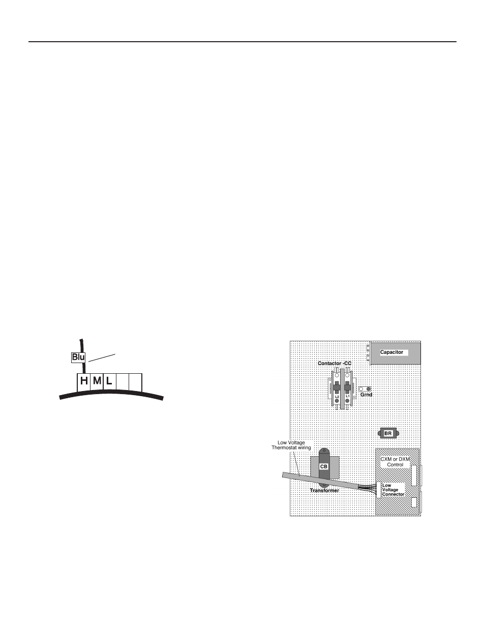
Blower Speed Selection – Units with PSC Motor
PSC (Permanent Split Capacitor) blower fan speed
can be changed by moving the blue wire on the fan
motor terminal block to the desired speed as shown
in Figure 16. Most Heat Controller units are shipped
on the medium speed tap. Consult submittal data or
engineering design guide for specific unit airflow tables.
Typical unit design delivers rated airflow at nominal
static (0.15 in. w.g. [37Pa]) on medium speed and rated
airflow at a higher static (0.4 to 0.5 in. w.g. [100 to 125
Pa]) on high speed for applications where higher static
is required. Low speed will deliver approximately 85%
of rated airflow at 0.10 in. w.g. [25 Pa]. An optional high
static blower is available on some models.
Electrical - Power & Low Voltage Wiring
Special Note for AHRI Testing: To achieve rated
airflow for ARI testing purposes on all PSC products,
it is necessary to change the fan speed to “HI” speed.
When the heat pump has experienced less than 100
operational hours and the coil has not had sufficient time
to be “seasoned”, it is necessary to clean the coil with a
mild surfactant such as Calgon to remove the oils left by
manufacturing processes and enable the condensate to
properly “sheet” off of the coil.
ELECTRICAL - LOW VOLTAGE WIRING
H M L
Azul
Fan Motor
Motor del Ventilador
Conectar el cable azul a:
H para velocidad de ventilador alta
M para velocidad de ventilador media
L para velocidad de ventilador baja
La configuración de fábrica es velocidad
media
Connect the blue wire to:
H for High speed fan
M for Medium speed fan
L for Low speed fan
Medium is factory setting
Fan Motor
Figure 16: PSC Motor Speed Selection
Figure 17: HB Low Voltage Field Wiring
Thermostat Connections
The thermostat should be wired directly to the
CXM board. Figure 17 shows wiring for HB units.
See “Electrical – Thermostat” for specific terminal
connections.
Low Water Temperature Cutout Selection
The CXM control allows the field selection of low water
(or water-antifreeze solution) temperature limit by clipping
jumper JW3, which changes the sensing temperature
associated with thermistor FP1. Note that the FP1
thermistor is located on the refrigerant line between the
coaxial heat exchanger and expansion device (TXV
or cap tube). Therefore, FP1 is sensing refrigerant
temperature, not water temperature, which is a better
indication of how water flow rate/temperature is affecting
the refrigeration circuit.
The factory setting for FP1 is for systems using water
(30°F [-1.1°C] refrigerant temperature). In low water
temperature (extended range) applications with
antifreeze (most ground loops), jumper JW3 should be
clipped as shown in Figure 18 to change the setting to
10°F [-12.2°C] refrigerant temperature, a more suitable
temperature when using an antifreeze solution. All
Heat Controller units operating with entering water
temperatures below 59°F [15°C] must include the
optional water/refrigerant circuit insulation package to
prevent internal condensation.