Comfort-Aire HBH Series 1/2 to 5 Ton User Manual
Page 12
IOM Instructions
HBH/V COMPACT
Heat Controller, Inc.
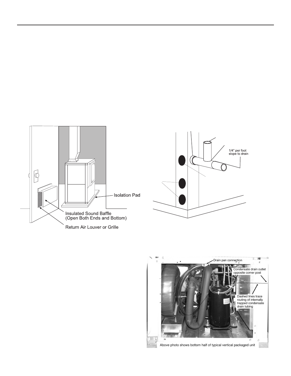
Vertical Installation
Sound Attenuation for Vertical Units
Sound attenuation is achieved by enclosing the unit within a
small mechanical room or a closet. Additional measures for
sound control include the following:
1. Mount the unit so that the return air inlet is 90° to the
return air grille. Refer to Figure 9. Install a sound baffle as
illustrated to reduce line-of sight sound transmitted through
return air grilles.
2. Mount the unit on a rubber or neoprene isolation pad to mini-
mize vibration transmission to the building structure.
Figure 9: Vertical Sound Attenuation
Condensate Piping – Vertical Units
Vertical units utilize a condensate hose inside the cabinet as
a trapping loop; therefore an external trap is not necessary.
Figure 10a shows typical condensate connections. Figure 10b
illustrates the internal trap for a typical vertical heat pump.
Each unit must be installed with its own individual vent (where
necessary) and a means to flush or blow out the condensate
drain line. Do not install units with a common trap and/or vent.
Vent
*3/4" IPT
3/4" PVC
Alternate
Condensate
Location
Water
Connections
(21mm per m)
* Some units include a painted drain connection. Using a
threaded pipe or similar device to clear any excess paint
accumulated inside this fitting may ease final drain line installation.
Figure 10a: Vertical Condensate Drain
Figure 10b: Vertical Internal Condensate Trap
NOTICE! Units with clear plastic drain lines should have
regular maintenance (as required) to avoid buildup of debris,
especially in new construction.