Figure 3-8. losw* and losw1 alarm reporting screen – ADC EMU-830 User Manual
Page 47
Chapter 3: Provisioning
3-15
Figure 3-8. LOSW* and LOSW1 Alarm Reporting Screen
8
Test the EMU’s dial-out alarm reporting as follows:
a. Configure the shelf alarms as instructed on
.
b. If necessary, select the Remote Alarm Reporting menu item and press ENTER to change the set-
ting from disable (Dis) to enable (Ena). See
c. Disconnect and re-connect an DSL Tip or Ring lead from a shelf. The shelf modem dials the man-
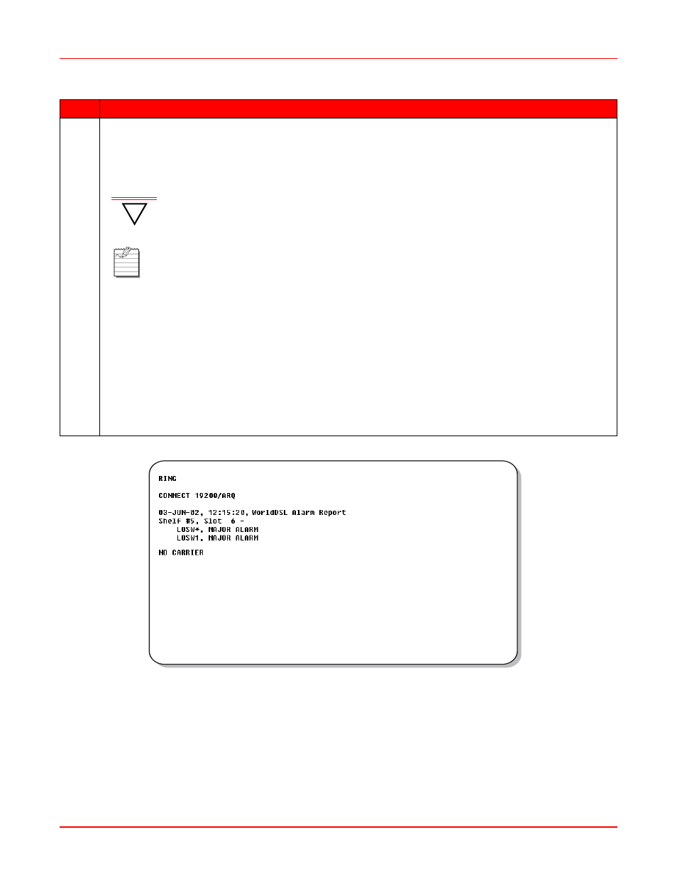
agement station, which displays the following alarms on its monitor:
shows that a loss of sync word occurred on both loops
(LOSW*) followed by a loss of sync word on Loop 1 only (LOSW1) and Loop 2 returning to normal
operation (that is, nothing displayed for Loop 2).
d. Disconnect and re-connect a G.703 interface cable from a shelf. The shelf modem dials the man-
agement station, which displays the following alarms on its monitor:
The alarm reporting screen in
shows that a loss of signal (LOS*), power
feed open (PFO*), and loss of sync word (LOSW*) occurred on both loops.
Step
Action
!
IMPORTANT
The following steps require that you momentarily disconnect an DSL Tip or Ring lead
and then a G.703 interface cable to test remote alarm reporting. Take steps to ensure
that a customer’s service is not interrupted.
Note:
The following alarm reporting screens are examples and do not represent the alarms
displayed in all tests.