Shelf modem for slip operation, Shelf modem for slip operation -9, Figure 2-7. modem to emu serial cable pinouts – ADC EMU-830 User Manual
Page 31: Slip o
2-9
S
HELF
M
ODEM
FOR
SLIP O
PERATION
One or more shelves can be remotely managed by connecting an external modem to the RS-232/RS-485 SLIP port.
However, when managed through the SLIP port, each shelf must be assigned a unique IP address (only one shelf is
accessed with each dial-up connection).
show WorldDSL shelves managed by SNMP
through SLIP.
To connect an external modem to the RS-232/RS-485 SLIP port:
4
Connect a serial cable (with pinouts as specified below) to the EMU console port connector (DB-9F) of
the local shelf.
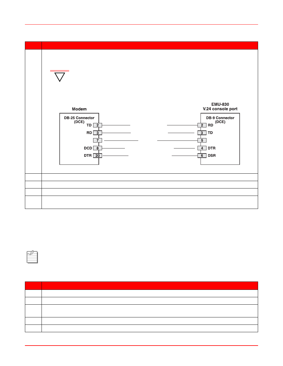
Figure 2-7. Modem to EMU Serial Cable Pinouts
5
Plug the other end of the cable into the serial port on the back of the modem.
6
At the back of the modem, plug a dedicated telephone line into the RJ-11 port labeled LINE or TELCO.
7
Plug the modem into an external power source and turn it on.
8
Configure the EMU modem parameters for remote alarm reporting as instructed in
(Configure and Test Dial-out Alarm Reporting)” on page 3-14
.
Note:
“EMU Jumper Settings” on page 2-1
for RS-232/RS-485 SLIP port configuration.
This procedure requires the use of a 25-wire straight-through cable, with a male DB-25 connector on each
end of the cable (see
).
Step
Action
1
Connect one end of the 25-wire cable to the RS-232/RS-485 (SLIP) connector on the EMS shelf.
2
Connect the other end of the cable to a standard modem.
3
If the modem has configuration switches or jumpers, set the switches or jumpers for factory default
operation. Refer to the modem user manual for more information.
4
At the back of the modem, plug a dedicated telephone line into the RJ-11 port labeled LINE or TELCO.
5
Plug the modem into an external power source and turn it on.
Step
Action
!
IMPORTANT
The modem-to-EMU serial cable must have the connector pinouts shown in
Figure 2-7 to function correctly.
RD (Receive Data)
TD (Transmit Data)
GND
DCD (Data Carrier Ready)
DSR (Data Set Ready)