Model icp, Recommended spare parts, spare pumps, 1 spare parts – Goulds Pumps ICP - IOM User Manual
Page 28
Installation, Operating and Maintenance Instruction
Model ICP
ICP 100-English
page 19
Revision 00
Article No 24264412
Issue
05/2006
Screws should be tightened, with the following
torque:
Screw torque in Nm
Location
Screw
Size
Lubricated
threads
Dry threads
M12 35
50
M16 105
150
Casing screws
M20 210
305
M10 35
50
M12 60
90
All other screws
M16 150
220
Before mounting the second bearing on the shaft
push in the circlip (932.51) between the two bear-
ings.
Before mounting new bearings, warm them up to
80°C in an oil bath or using a bearing heater. If
necessary use a tube to force the inner ring onto
the shaft by gentle taps with a hammer. Hold the
outer ring to avoid vibrations of the balls.
When bolting together the bearing bracket (330)
with the bearing bracket lantern (344) and the
bearing bracket lantern with the volute casing
(102V), screws should be positioned in the centre
of the drilled holes. Failure to do so could result in
improper oil setting.
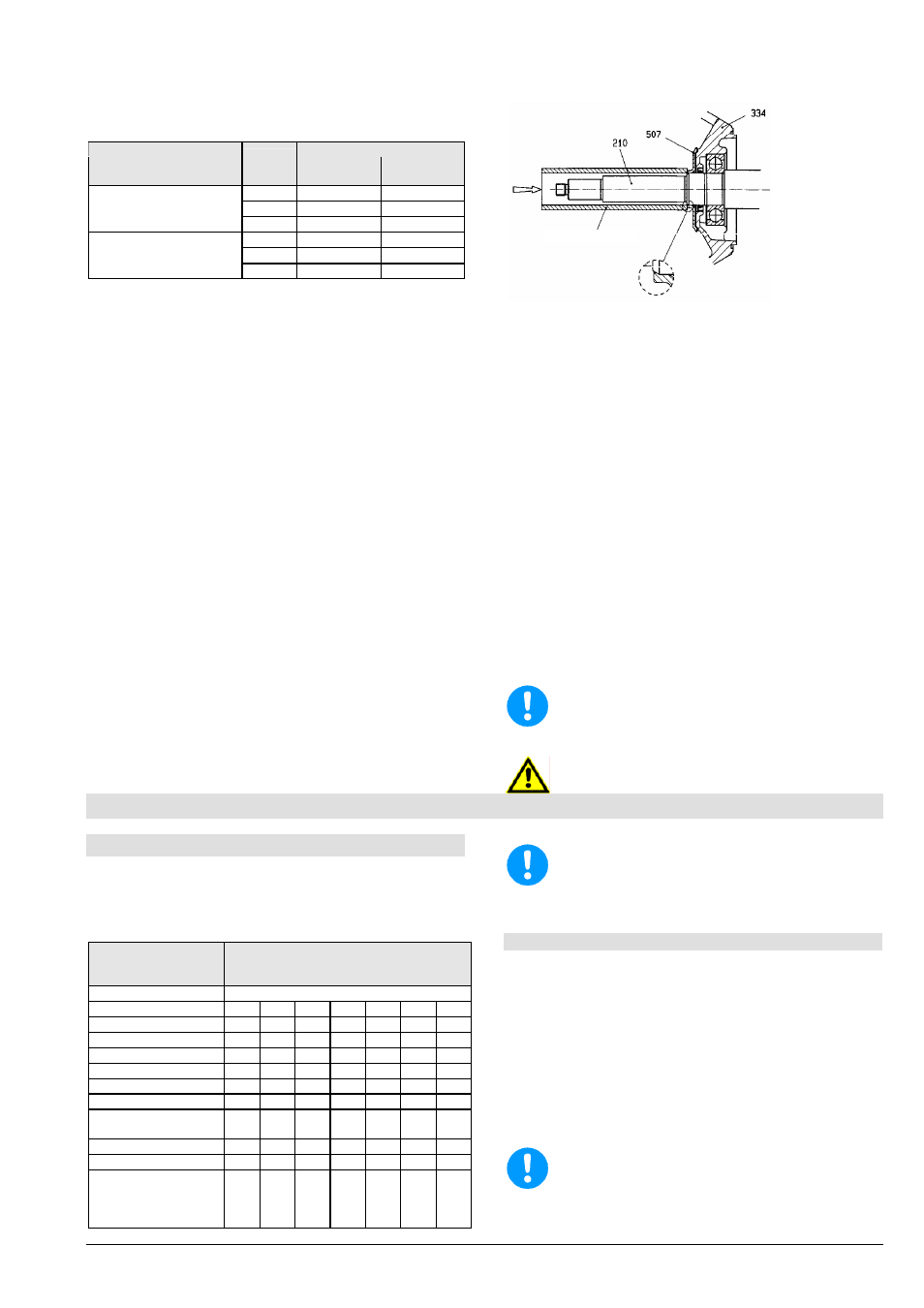
Push the flinger (507) onto the shaft (210) till it
rests axially against the shoulder of the shaft. Be-
tween flinger (507) and Bearing bracket lantern
(344) there must remain a clearance of at least
0,7 mm.
If necessary you can use a driver for mounting
(see picture 14).
pic 14
Do not use excessive force.
For mounting of the shaft sealing (packing or me-
chanical sealing) see separate description
"Mounting Instruction of Shaft Sealing" and chap-
ter 8.5.
For impellers with back vanes the axial clearance
between the back vanes and the casing cover
(161) should be checked after mounting the im-
peller (230) and tightening the impeller nut (922)
(see chapter 8.7.1).
After the mounting of the back pull out assembly,
and its assembly into the volute casing, turn the
shaft and control the free moving of the pump in
this way. The shaft sealings will cause slightly re-
sistance when turning, but there must not be any
contact between metal parts.
Before starting the pump check alignment of the
coupling. This can be dropped on pumps with
spacer coupling, if pump casing and motor were
not disassembled.
Before starting the pump do not forget to fill in
oil!
Before starting the pump do not forget to install
and connect all security devices.
9. Recommended Spare Parts, Spare Pumps
9.1 Spare Parts
Spare parts should be selected to last for two-years
continuous operation. If no other guidelines are appli-
cable, we recommend that you stock the number of
parts listed below (in accordance with DIN 24296).
Number of pumps
(incl. stand-by pumps)
2 3 4 5 6/7 8/9 10/+
Spare Parts
Number of Spare Parts
Impeller
1 1
1 2 2
2
20%
Wear
ring
2 2
2 3 3
4
50%
Shaft with key and nuts
1
1
1
2
2
2
20%
Ball Bearing set
1
1
2
2
2
3
25%
Shaft
sleeve
2 2
2 3 3
4
50%
Lantern
ring
1 1
2 2 2
3
30%
Packing
ring
16 16
24 24 24
32
100%
Joints for pump casing
sets
4 6
8 8 9
12
150%
other joints sets
4
6
8
8
9
10
100%
Mech. Seals
set
1
1
2
2
2
3
25%
Bearing (lantern with
bearing bracket, com-
plete with shaft, bear-
ings, aso.)
- - - - - - 2
To ensure optimum availability, we recommend
that suitable quantities of spare parts are held
in stock, especially if these are made from spe-
cial materials and in the case of mechanical
seals, because of the longer delivery times.
Spare Parts Order
When ordering spare parts, please supply the follow-
ing information:
Type:
______________________________________________________________________
S/N (Order No.):
_
___________________________________________________
Part
name:
_____________________________________________________________
Sectional
Drawing
__________________________________________________
All the information is given in the data sheet and the
relevant sectional drawing.
Store spare parts in dry and clean rooms!
Driver