Model icp, Dismantling and repair of pump, 6 cleaning of pump – Goulds Pumps ICP - IOM User Manual
Page 25: 1 general remarks, 2 general, 3 disassembly of back pull out assem- bly
Installation, Operating and Maintenance Instruction
Model ICP
ICP 100-English
page 16
Revision 00
Article No 24264412
Issue
05/2006
least 1x year, the radial clearance in the coupling
parts must be checked.
For couplings with rubber pads the following applies:
Unless a clearance in the couplings is necessary, the
coupling pads may wear out to approximately ¼ of
their usual thickness, before they have to be changed.
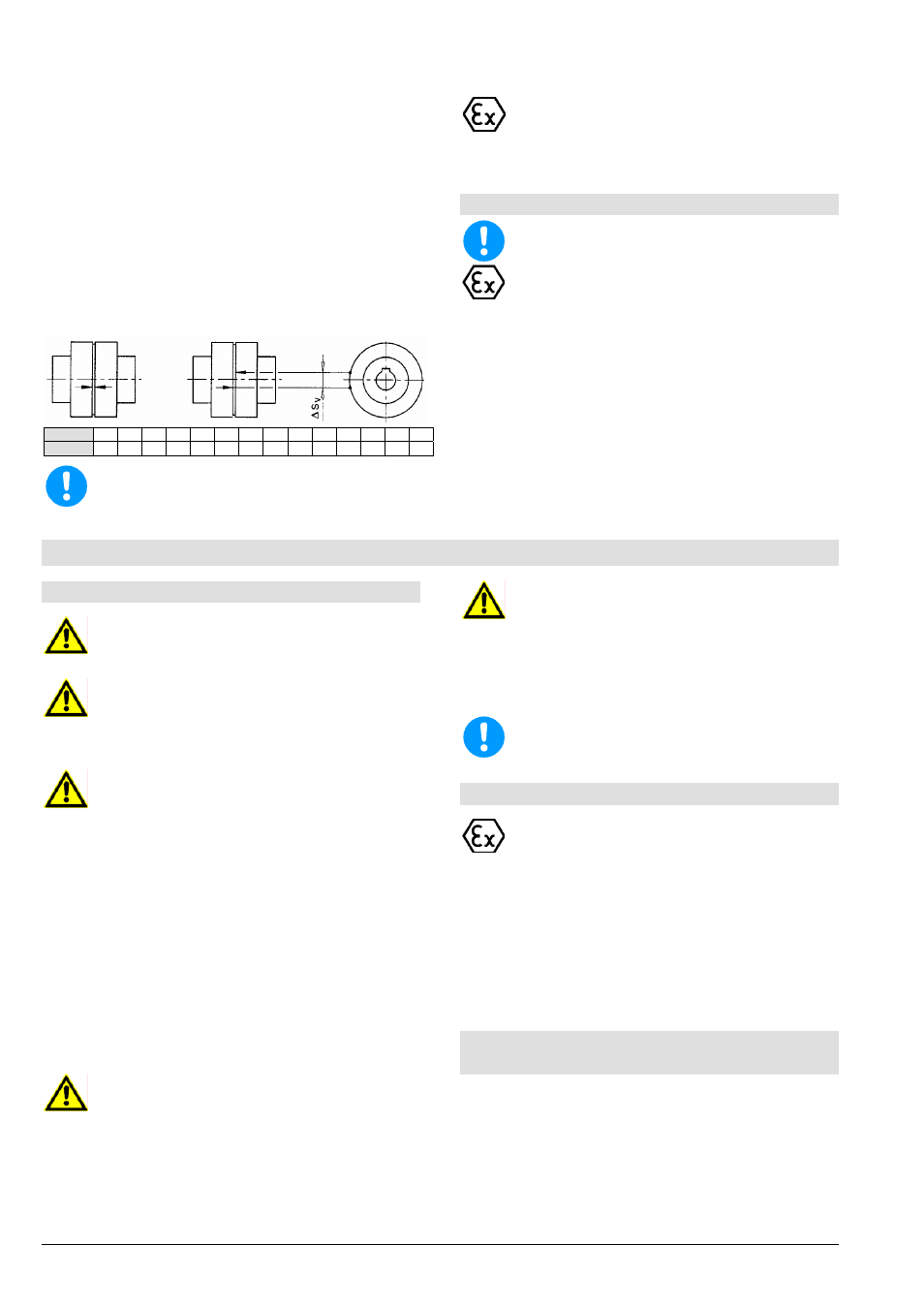
To measure the clearance in the coupling place a
mark on the O.D. of each coupling hub (see following
pic). Then fixing one hub, turn the opposite hub as far
as possible. Then measure the distance (
∆S
V
) be-
tween the marks of the coupling. If this measure ex-
ceeds the value given in the chart, the packings must
be replaced. They must be replaced in sets.
Size
80 95 110 125 140 160 180 200 225 250 280 315 350 400
∆S
v
[mm] 5,0 6,0 7,0 8,0 8,5 8,0 8,0 8,5 9,0 10,0 11,5 10,5 11,5 13,0
If wear is heavy, it must be assumed that the
motor is not properly aligned with the pump or
that the distance between the coupling sections
has changed. Replace worn elements and re-
install or adjust coupling, as described in chap-
ter 5.3.
7.6 Cleaning of pump
The pump must not be cleaned with pressur-
ised water - water will get into the bearings.
Dirt on the outside of the pump has an adverse
effect on transmission of heat. The pump should
therefore be cleaned with water at regular inter-
vals (depending on the degree of dirt).
Radial-Shaft sealings (421.41 and 421.51) are not
completely free from leakage. Impurities could
cause leakage at the shaft sealing area of the
frame. Therefore wipe off impurities with a rag
from time to time.
Replace dirty oil level sight glass (642).
8. Dismantling and repair of pump
8.1 General remarks
Repair to the pump or pump system may only
be carried out by authorised skilled personnel
or by the manufacturer´s specialist staff.
When disassembling the pump pay attention to
chapter 2 and chapter 4.1.
For mounting and repair you can order specialized
personnel if you want.
If dangerous liquids are pumped the appropri-
ate disposal of the handled liquid is necessary
before the disassembly of the pump. Pay atten-
tion to the fact, that even in drained pumps
there are remainders of the handled liquid. If
necessary the pump must be flushed or decon-
taminated. Laws must be observed, otherwise
danger to health is existing!
Before the disassembly the pump has to be se-
cured in such a way, that it can´t be started.
The pump casing must be drained and without
pressure.
All locking devices in the suction- and discharge-
pipe must be closed.
All parts must have taken on the temperature of
the environment.
Secure disassembled pumps, units or single
parts against tipping over or rolling off.
While disassembling the pump use of an open
flame (blowlamp, etc.) only, when there is no
danger of setting fire, cause an explosion or
cause injurious vapours.
Never apply heat to remove the impeller nut.
Use of heat may result in severe physical injury
and property damage.
Use original spare parts only. Pay attention to
the right materials and the matching design.
8.2 General
Works, which require shocks (hammer), must
only be performed outside the explosive at-
mosphere or only non-sparking tools must be
used.
Carry out disassembly and mounting according to the
appropriate sectional drawing.
You will only need common tools.
Before disassembly check if required parts are ready.
Disassemble the pump only so far, as required for the
replacement of the repair part.
8.3 Disassembly of Back Pull Out Assem-
bly
The Back Pull Out Assembly includes all parts of the
pump except the volute casing (102V). As the pumps
are constructed for process design the volute casing
(102V) can stay on the base frame and in the pipes,
unless the volute casing itself must be repaired.
Drain volute casing (102V) through the drain plug
(912.11).