Goulds Pumps 7200CB - IOM User Manual
Page 27
Installation
1. Shims
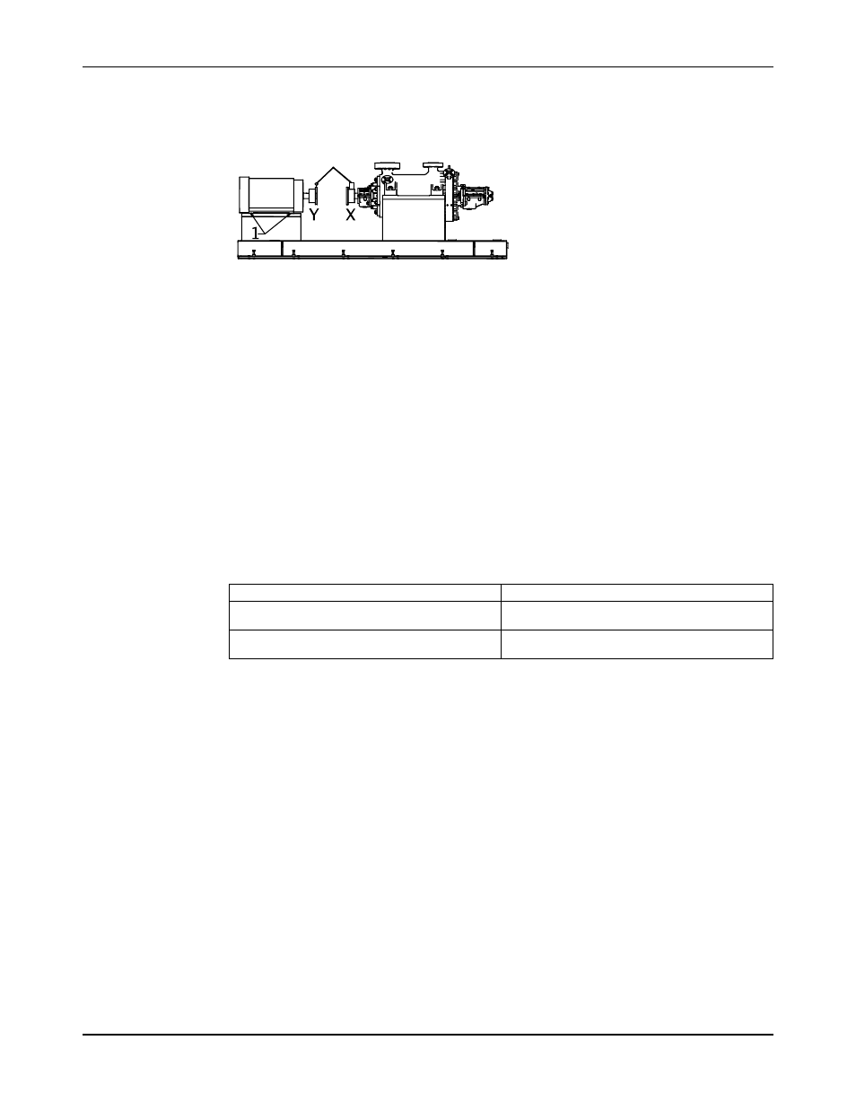
Figure 8: Example of incorrect vertical alignment (side view)
4. Repeat the previous steps until the permitted reading value is achieved.
Perform parallel alignment for a horizontal correction
A unit is in parallel alignment when the parallel indicator (P) does not vary by more than
0.002 in. (0.05 mm) as measured at four points 90° apart at the operating temperature.
1. Set the parallel alignment indicator (P) to zero on the left side of the driver coupling half (Y),
90° from the top-center position (9 o’clock).
2. Rotate the indicator through the top-center position to the right side, 180° from the start
position (3 o’clock).
3. Record the indicator reading.
When the reading value is...
Then...
Negative
The driver coupling half (Y) is to the left of the
pump coupling half (X).
Positive
The driver coupling half (Y) is to the right of the
pump coupling half (X).
4. Slide the driver carefully in the appropriate direction.
Model 7200CB, API Type BB5 Barrel Multistage / ISO 13709 2nd Edition / API 610 11th Edition Installation, Operation, and
25
Maintenance Manual