Goulds Pumps 7200CB - IOM User Manual
Page 25
Installation
2. Rotate the pump coupling half (X) in order to check that the indicators are in contact with
the driver coupling half (Y) but do not bottom out.
3. Adjust the indicators if necessary.
Perform angular alignment for a vertical correction
1. Set the angular alignment indicator to zero at the top-center position (12 o’clock) of the
driver coupling half (Y).
2. Rotate the indicator to the bottom-center position (6 o’clock).
3. Record the indicator reading.
When the reading value is...
Then...
Negative
The coupling halves are farther apart at the
bottom than at the top. Perform one of these
steps:
• Add shims in order to raise the feet of the
driver at the shaft end.
• Remove shims in order to lower the feet of the
driver at the other end.
Positive
The coupling halves are closer at the bottom than
at the top. Perform one of these steps:
• Remove shims in order to lower the feet of the
driver at the shaft end.
• Add shims in order to raise the feet of the
driver at the other end.
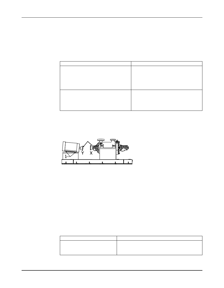
1. Shims
Figure 6: Example of incorrect vertical alignment (side view)
4. Repeat the previous steps until the permitted reading value is achieved.
Perform angular alignment for a horizontal correction
1. Set the angular alignment indicator (A) to zero on left side of the driver coupling half (Y),
90° from the top-center position (9 o’clock).
2. Rotate the indicator through the top-center position to the right side, 180° from the start
position (3 o’clock).
3. Record the indicator reading.
When the reading value is...
Then...
Negative
The coupling halves are farther apart on the right side than
the left. Perform one of these steps:
• Slide the shaft end of the driver to the left.
• Slide the opposite end to the right.
Model 7200CB, API Type BB5 Barrel Multistage / ISO 13709 2nd Edition / API 610 11th Edition Installation, Operation, and
23
Maintenance Manual