Goulds Pumps 3408 - IOM User Manual
Page 60
54
3408 IOM 03/99
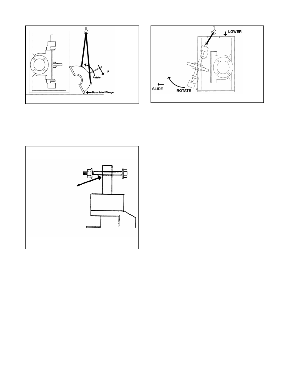
Rotating Element Removal
12. For these procedures it will be necessary to remove
the line shafting or motor. Then remove the pump half
coupling.
13. Thread a long bolt, washer and nut through the hole
at the end of the shaft. (See Fig. 56)
14. Sling around eye bolt, putting slight amount of
tension on sling.
15. Remove restraining straps if rotating element is not
securely fastened to casing lower half.
16. Lightly tapping on inboard and outboard bearing
housings, slide rotating element away from lower half.
17. Lower rotating element to ground by sliding outboard
bearing housing away from pedestal enabling element
to be set on floor with shaft in an horizontal position.
(See Fig. 57)
18. Rotating element can now be serviced following
disassembly procedure given previously in this
manual.
Reassembly of Rotating Element
19. Inspect main joint gasket and replace if
necessary. (Follow replacement instructions in
disassembly procedures section.)
20. Sling around the bolt in end of pump shaft.
21. On full pedestals, the lifting sling must come
through hole in top plate of pedestal.
(See Fig. 57)
22. When rotating element is off the ground and in
the vertical position, align any anti-rotation pins in
the casing rings and stuffing boxes for proper
orientation in the slots in the casing lower half.
23. Moving element towards casing lower half,
engage the stuffing box tongue first.
24. As the stuffing box tongue begins to go into the
respective casing fit, raise the inboard bearing
housing into its respective fit.
25. When the stuffing box tongues are firmly seated
in their respective fits and all the anti-rotation pins
are seated in their slots, restrain the rotating
element to the lower half.
Replacing Upper Casing Half
26. Sling around lifting ears and with stabilizer bar
installed, pick casing upper half off the ground
and rotate top half so that main joint flange is
vertical. (Reference Fig. 55 with rotation in
opposite direction shown.)
27. Move upper half towards lower half.
28. Prior to complete engagement of upper half onto
lower half, use dowel pins to guide the upper half
into its final exact position.
Fig. 55
Fig. 57
Fig. 56
COUPLING END OF
S H A F T D R I L L E D
THRU FOR A LONG
BOLT WITH NUT &
WASHER